X7056_Operating manual_en.pdf - 第49页
Product description Energy supply and interfaces 49 Inspection system X7056 | Operating manual | Version 3.1 Rev.006| 2016-01-06 | 30.009.1930a The communication is ended when the acceptance is successful. Configurable a…
Product description
Energy supply and interfaces
48
Inspection system X7056 | Operating manual |
Version 3.1 Rev.006| 2016-01-06 | 30.009.1930a
Overview
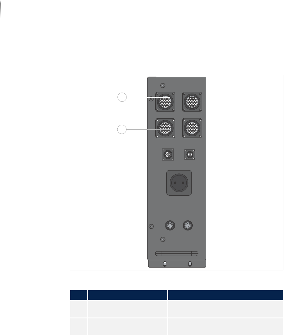
The connection plugs for the interface protocols are located behind
the front door of the system. Depending on requirements, either
SMEMA or SV-70 connection plugs are available.
SMEMA/SV70 connection plugs
SMEMA
The SMEMA protocol consists of two signals:
Request: Is set when a PCB is ready for transfer.
Permission: Is set when a device is ready to accept a PCB.
The communication is ended when both signals are returned.
SV70
The SV70 protocol consists of four signals:
Request: Is set when a PCB is ready for transfer
.
Permission: Is set when a device is ready to accept a PCB.
Released: Is set when a PCB is released
.
Accepted: Is set when a PCB is accepted.
SMEMA/SV70 connection plugs
No. Name Description
1 n-1A Communication with the transport
track on the infeed side.
2 n+1A Communication with the transport
track on the outfeed side.
1
2
Product description
Energy supply and interfaces
49
Inspection system X7056 | Operating manual |
Version 3.1 Rev.006| 2016-01-06 | 30.009.1930a
The communication is ended when the acceptance is successful.
Configurable
additional
signals
Some of the signals described are available optionally and must
correspondingly be configured. Additional signals may be present.
Product change signal: notifies the next device about a product
change. The inspection system waits until the next device
acknowledges the product change.
Malfunction loop: signals preceding devices that there is a
malfunction in the system and that a PCB might not be
accepted. The specific design of the malfunction loop is a
customer-specific configuration.
NOTICE
Setting the additional signals may only be done by Viscom service
technicians.
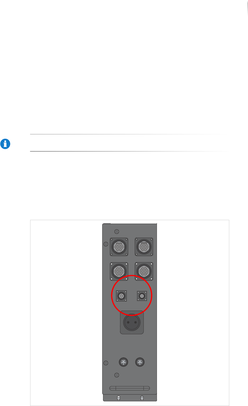
Interlock linkage
The Interlock chain ensures the inspection is stopped as soon as
an adjacent system interrupts the Interlock circuit.
The Interlock connection plugs are located behind the front door of
the system.
Interlock connection plugs?

Product description
Energy supply and interfaces
50
Inspection system X7056 | Operating manual |
Version 3.1 Rev.006| 2016-01-06 | 30.009.1930a
The connections for the Interlock linkage are equipped with
jumpers.