X7056_Operating manual_en.pdf - 第67页
Installation 67 Inspection system X7056 | Operating manual | Version 3.1 Rev.006| 2016-01-06 | 30.009.1930a Installation This chapter describes the proper way to install the inspection system. It contains the fol lowing …
Delivery
Unpacking the inspection system
66
Inspection system X7056 | Operating manual |
Version 3.1 Rev.006| 2016-01-06 | 30.009.1930a
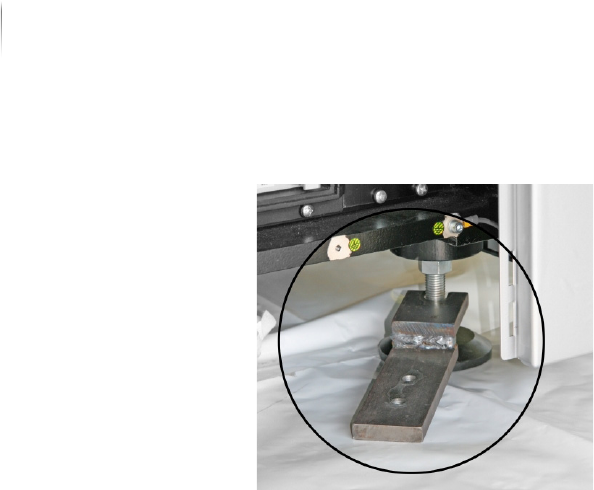
2. Pull out the transport clamp.
3. Repeat steps 1 to 2 for the other 3 transport clamps.
The transport clamps are removed. The inspection system can
now be taken to its final usage site.

Installation 67
Inspection system X7056 | Operating manual |
Version 3.1 Rev.006| 2016-01-06 | 30.009.1930a
Installation
This chapter describes the proper way to install the inspection
system.
It contains the following sections:
Safety (Page 68)
Mechanical installation (Page 69)
Electrical installation (Page 78)
Integrating the inspection system into the line (Page 82)
First use (Page 91)

Installation
Safety
68
Inspection system X7056 | Operating manual |
Version 3.1 Rev.006| 2016-01-06 | 30.009.1930a
Safety
Follow these instructions when installing the system:
The inspection system must stand on a flat, even, horizontal
surface.
The setting conditions must be met, see „Setting conditions“
(Page 69).
The mechanical and electrical installation may only be done by
trained specialists or by Viscom AG service technicians.
A minimum free space of 1 m in front of and behind the inspec-
tion system is required for installation work.
All supply lines must be laid or hung so that the operation of
the system is not hindered, no cause of stumbling exists, and
the required minimum clearance is observed.
The system may not be operated with a disconnected PE safety
conductor under any circumstances, see „Checking the safety
conductor PE“ (Page 80).
The contact current in the inspection system is more than
3.5 mA. In addition to the safety conductor PE a separate
ground/earth connection attached to the PE clamp is manda--
tory, see „Connecting FE (TE)“ (Page 80).
Immediately after the setup work is finished, check all safety
features.
The protective features installed by the Viscom AG may not be
altered, bypassed or disabled in any way.