X7056_Operating manual_en.pdf - 第75页
Installation Mechanical installation 75 Inspection system X7056 | Operating manual | Version 3.1 Rev.006| 2016-01-06 | 30.009.1930a 4. Remove the two screws of the second AXI tr ansport lock (6 mm hex key). 5. Remove the…
Installation
Mechanical installation
74
Inspection system X7056 | Operating manual |
Version 3.1 Rev.006| 2016-01-06 | 30.009.1930a
ATTENTION
Damage to the inspection system
Unsecured transport axes may cause damage during transport.
Only remove the transport locks when the system is at its final
installation site.
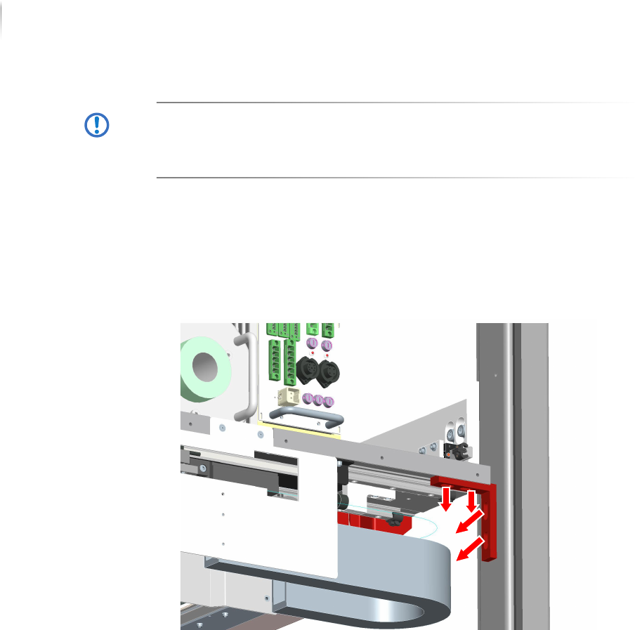
Perform the following work steps:
1. Open the rear swing doors.
Access to the AXI section is open.
2. Remove the four screws of the first AXI transport lock (6 mm
hex key).
3. Remove the first AXI transport lock.
Installation
Mechanical installation
75
Inspection system X7056 | Operating manual |
Version 3.1 Rev.006| 2016-01-06 | 30.009.1930a
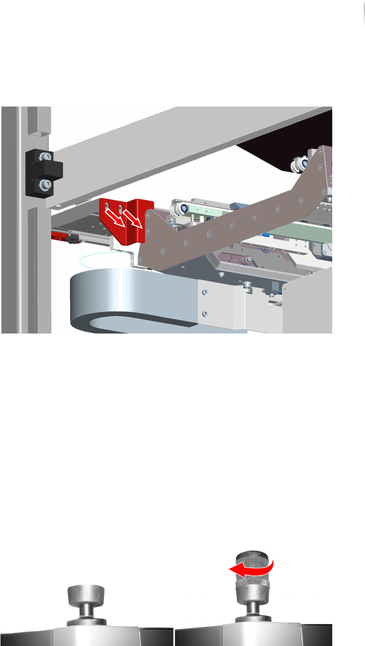
4. Remove the two screws of the second AXI transport lock (6 mm
hex key).
5. Remove the second AXI transport lock.
The AXI transport locks are removed.
Installing the signal lamp
Perform the following work steps:
1. Take the signal lamp light elements out of the accessories
carton.
2. Set the light element into the signal lamp socket.
3. Turn the light element carefully into its socket until it locks.
4. Complete steps 1 to 3 for the X-ray signal lamp also.
The signal lamps are installed.
Installation
Mechanical installation
76
Inspection system X7056 | Operating manual |
Version 3.1 Rev.006| 2016-01-06 | 30.009.1930a
Level the housing to horizontal
Required: Carpenter's level
Two 24mm open end wrench
NOTICE
It is also possible to work with two levels at the same time. Set
one level on the upper side of the housing in the X-direction and
the other in the Y-direction and level the system.
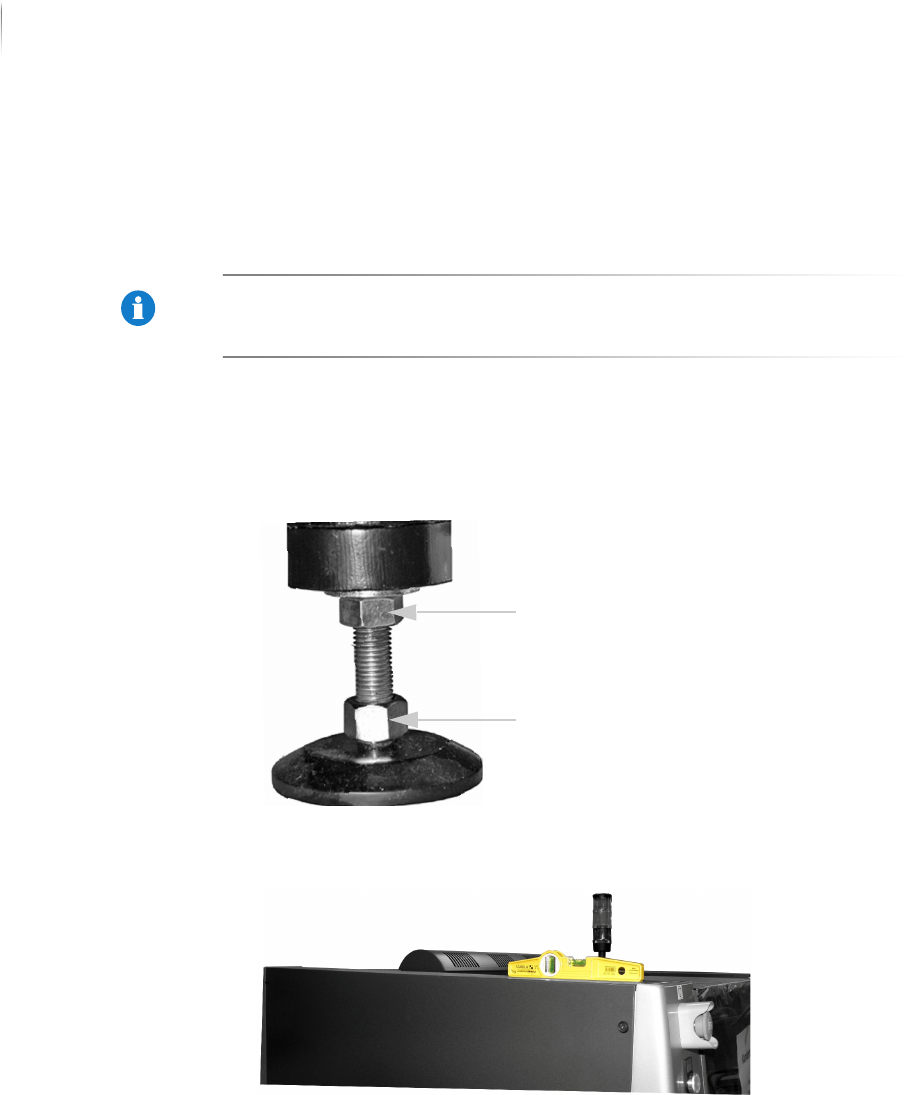
Perform the following work steps:
1. Loosen the lock nuts on the housing feet.
The housing feet can now be turned in or out by their lower
bolts.
2. Set the level on the upper side of the housing in the y-direc-
tion.
3. Set the inspection system in a horizontal position as indicated
by the level by turning in or out the housing feet.
The level indicates whether the system is horizontally level.
Lock nut
Screw