X7056_Operating manual_en.pdf - 第78页
Installation Electrical inst allation 78 Inspection system X7056 | Operating manual | Version 3.1 Rev.006| 2016-01-06 | 30.009.1930a Electrical installation This section describes the proper electrical installation of th…
Installation
Mechanical installation
77
Inspection system X7056 | Operating manual |
Version 3.1 Rev.006| 2016-01-06 | 30.009.1930a
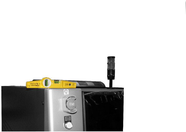
4. Set the level on the upper side of the housing in the x-direc-
tion.
5. Set the inspection system in a horizontal position as indicated
by the level by turning in or out the housing feet.
The level indicates whether the system is horizontally level.
6. Repeat steps 1 to 5 for all four edges of the upper side of the
housing.
7. Check if the sensor head collides with the housing by moving it
to all end positions.
? Does the sensor head collide with the housing?
Adjust the system feets until the sensor head does not collide
with the housing any more.
8. Fasten the lock nuts of the housing feet with an open-end
wrench while re-tightening the screws with a second open-end
wrench.
The housing of the inspection system is levelled to horizontal.
Installation
Electrical installation
78
Inspection system X7056 | Operating manual |
Version 3.1 Rev.006| 2016-01-06 | 30.009.1930a
Electrical installation
This section describes the proper electrical installation of the
inspection system.
The following steps are described:
Electrical specifications (Page 78)
Providing a standard connection (Page 78)
Checking the safety conductor PE (Page 80)
Connecting FE (TE) (Page 80)
Check motor overload switch settings (Q1EA) (Page 81)
Electrical specifications
NOTICE
The system can optionally be equipped with a network trans-
former, see „Product description“ > „Network transformer“
(Page 37).
Providing a standard connection
Precondition: The inspection system is connected to the power supply with a
16A/6 h CEE plug.
The inspection system requires the following electrical connec-
tion: 230/400 V AC, 50/60 Hz, 3 phase, N, PE
The main switch is set to OFF.
The connection requirements are met, see section „Electrical
specifications“ (Page 78).
Electrical specifications
Power supply 230/400 VAC, 50/60 Hz, 3 phase, N, PE
Power supply with internal
transformer for main power
adaptation
190 V - 600 VAC, 50/60 Hz, 3 P/N/PE
Average power consumption 0.78 kW/h
Max. Power 1.5 kW
Min. Power 0.62 kW
Motor overload switch See current circuit diagram
Automatic cutout 8 A characteristic "C"
Installation
Electrical installation
79
Inspection system X7056 | Operating manual |
Version 3.1 Rev.006| 2016-01-06 | 30.009.1930a
The inspection system is properly set in place.
NOTICE
Each system must be assigned a separate leakage circuit breaker.
DANGER
Electrical shock
Danger to life from improper conduct.
Before all electrical work, make sure that:
the main power supply is disconnected and
the system is protected from accidental switching-on.
CAUTION
Danger of tripping
Injury due to improperly laid cable.
When laying the cable, make sure there are no kinks, places to
trip or tangles.
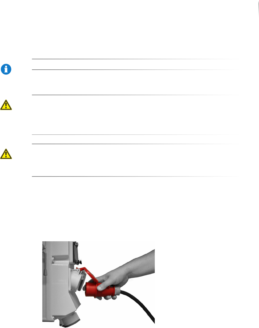
Perform the following work steps:
1. Open the rear swing doors of the inspection system.
2. Take the connection cable with the CEE plug.
3. Connect the inspection system to the main electrical power
supply.
The standard connection is done.