X7056_Operating manual_en.pdf - 第81页
Installation Electrical in stallation 81 Inspection system X7056 | Operating manual | Version 3.1 Rev.006| 2016-01-06 | 30.009.1930a 4. Latch the front door . FE (TE) is connected. Check motor overload switch sett ings…
Installation
Electrical installation
80
Inspection system X7056 | Operating manual |
Version 3.1 Rev.006| 2016-01-06 | 30.009.1930a
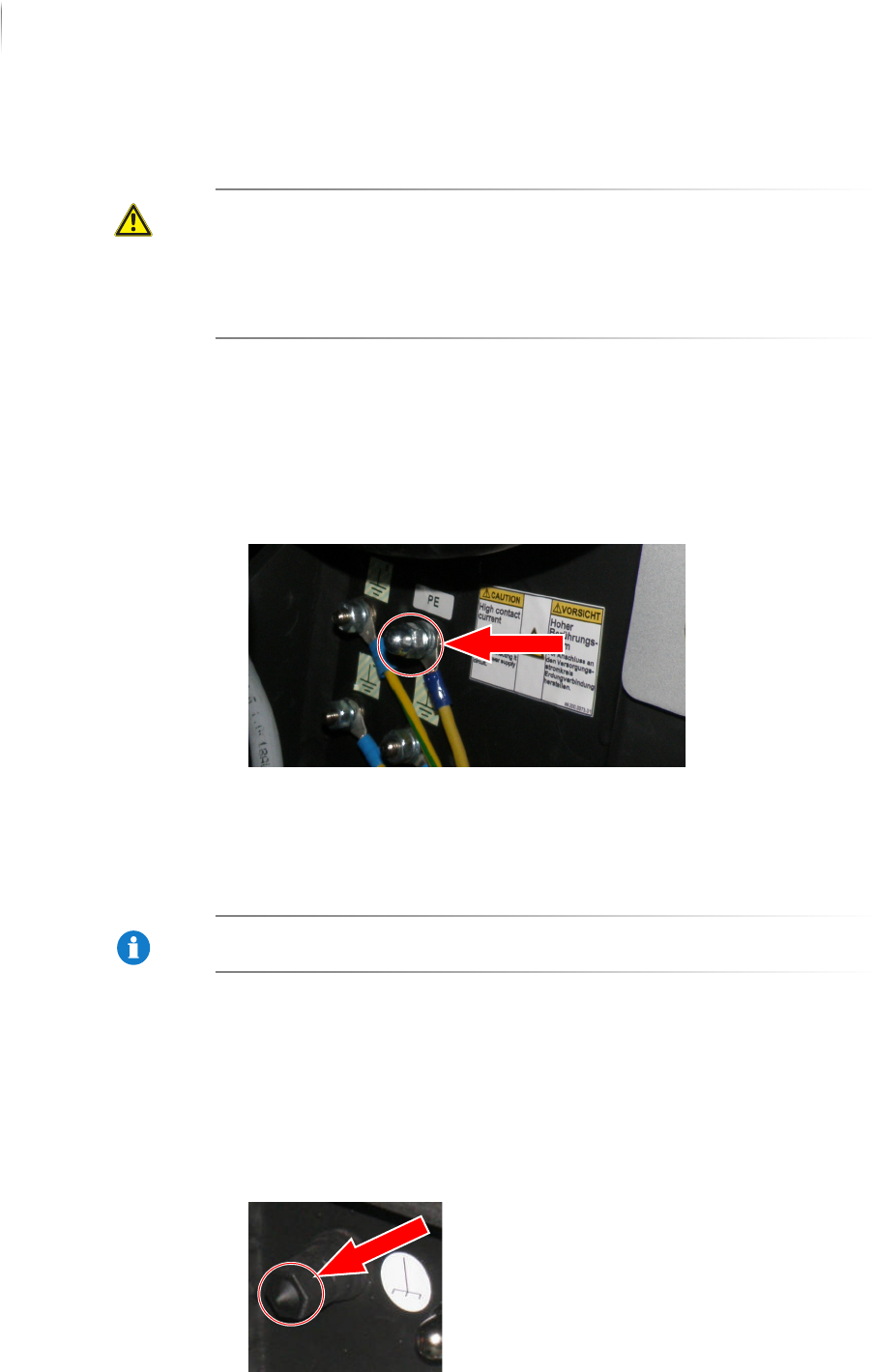
Checking the safety conductor PE
DANGER
Electrical shock
Danger to life from disconnected safety conductor.
The safety conductor must be connected to prevent electrical
shock.
The system may not be operated with a disconnected safety
conductor under any circumstances.
Perform the following work steps:
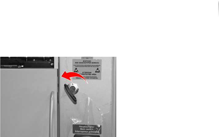
1. Open the front door.
2. Open the pivoting frame, see „Open the pivoting frame“ (Page
87).
3. Make sure that the safety conductor is properly connected.
The safety conductor is checked.
Connecting FE (TE)
NOTICE
The FE (TE) connection improves electromagnetic compatibility
(EMC).
Perform the following work steps:
1. Open the front door.
2. Open the pivoting frame, see „Open the pivoting frame“ (Page
87).
3. Connect a flexible conductor with a minimum cross section of
10 mm
2
, which is connected to the potential equalization point.
Installation
Electrical installation
81
Inspection system X7056 | Operating manual |
Version 3.1 Rev.006| 2016-01-06 | 30.009.1930a
4. Latch the front door.
FE (TE) is connected.
Check motor overload switch settings (Q1EA)
Perform the following work steps:
1. Use the current circuit diagram to make sure that the fuses
correspond to the input voltage.
2. Adjust the settings, if required.
The motor overload switch is adjusted.
Installation
Integrating the inspection system into the line
82
Inspection system X7056 | Operating manual |
Version 3.1 Rev.006| 2016-01-06 | 30.009.1930a
Integrating the inspection system into the
line
After the system is installed and then connected, integrate it into
the production line.
The work steps in detail:
Engineering Drawings (Page 82)
Adjusting the height of the inspection system (Page 84)
Leveling the inspection system to horizontal (Page 85)
Adjusting the transport track width (Page 86)
Checking the transport track width (Page 87)
Communication with adjacent devices (Page 87)
Network connection (Page 89)
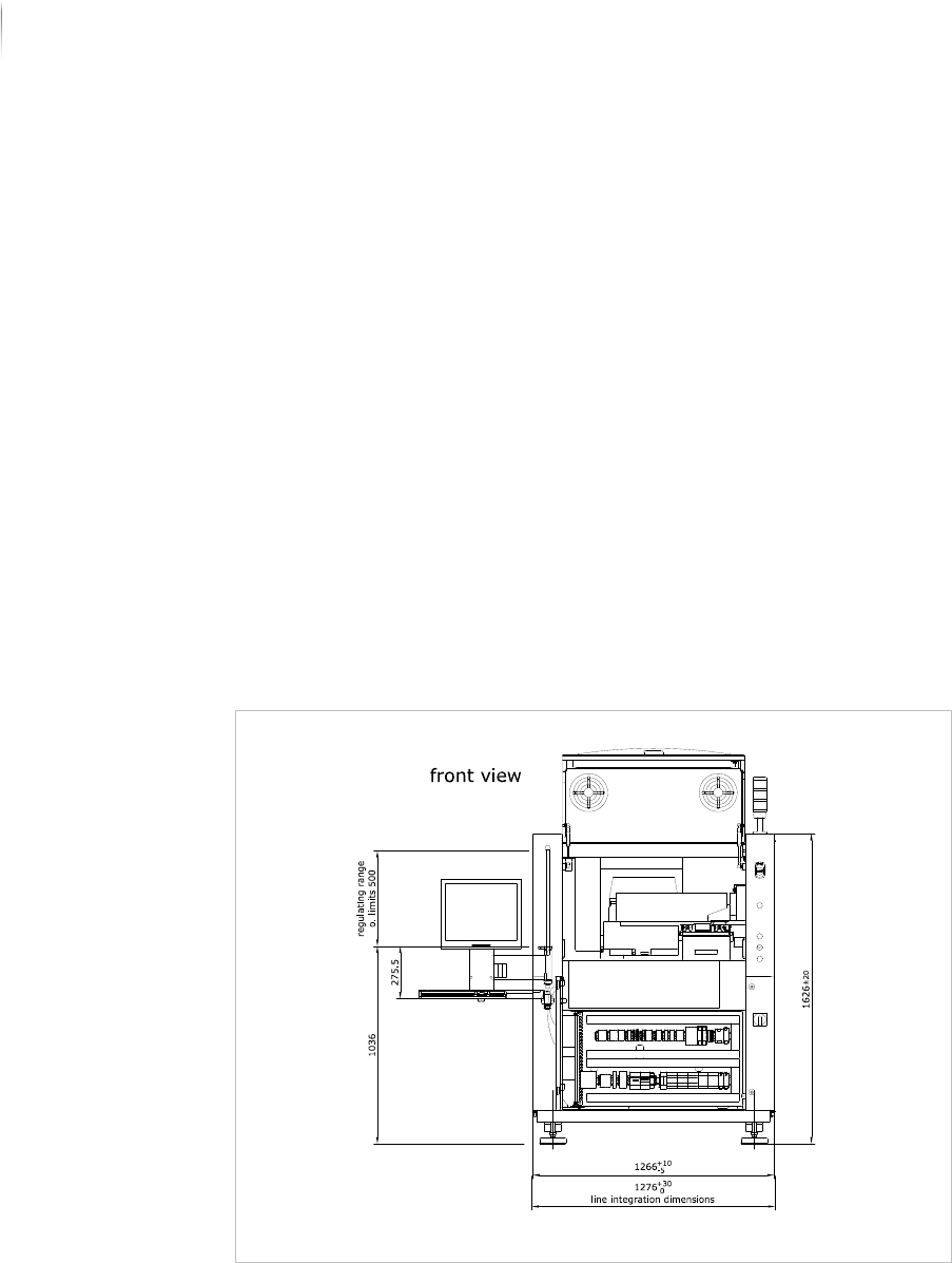
Engineering Drawings
The following drawings assist integration into the line.
Line integration: front view