X7056_Operating manual_en.pdf - 第88页
Installation Integrating th e inspection system into the line 88 Inspection system X7056 | Operating manual | Version 3.1 Rev.006| 2016-01-06 | 30.009.1930a Perform the following work steps: 1. Open the front door . 2. U…
Installation
Integrating the inspection system into the line
87
Inspection system X7056 | Operating manual |
Version 3.1 Rev.006| 2016-01-06 | 30.009.1930a
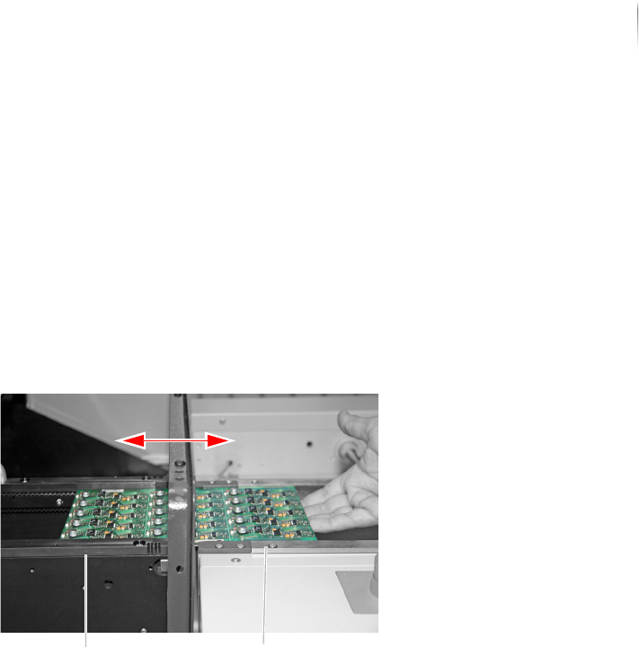
Checking the transport track width
Perform the following work steps:
1. Place a PCB in the inspection system transport track that
adjoins the external transport conveyor of the production line.
2. Slide the PCB back and forth between inspection system and
conveyor belt.
The printed circuit board should not catch or get stuck, but
should be easy to slide between inspection system and trans-
port conveyor.
? Is the PCB difficult to move?
The transport track width is too narrow.
Set the transport track width, see step „Adjusting the trans-
port track width“ (Page 86).
The transport track width is checked.
Communication with adjacent devices
The communication with adjacent devices is provided by the
SMEMA/SV70 protocols and the Interlock linkage.
The following sections describe how to establish connection with
adjacent devices, step by step:
Open the pivoting frame (Page 87)
Connecting SMEMA/SV70
Linking the inspection system via Interlock
Open the
pivoting
frame
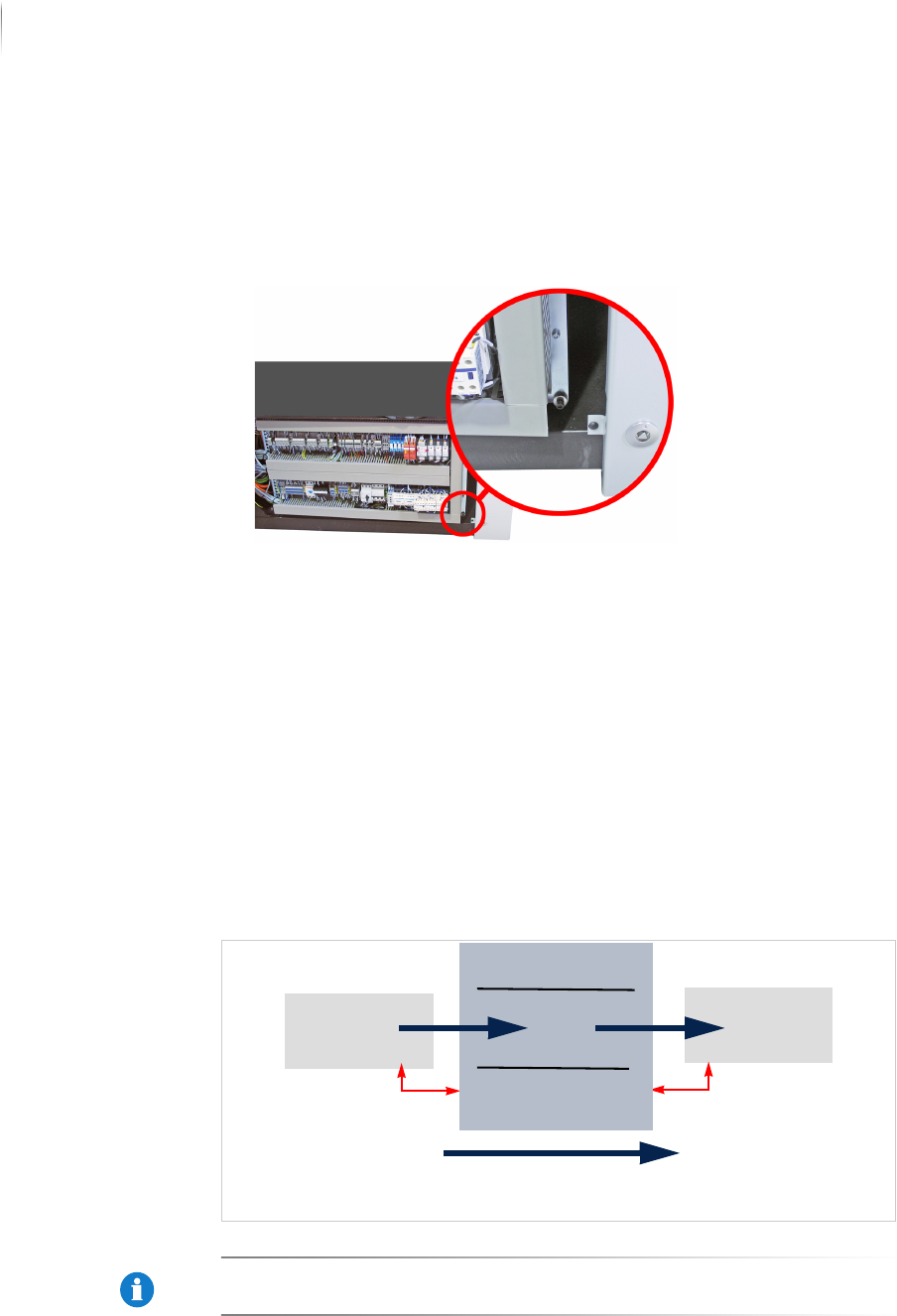
To get access to the communication plugs you have to open the
pivoting frame.
Required: 6 mm Allen (hex) key
Transport conveyor,
inspection system
Transport conveyor,
production line
Installation
Integrating the inspection system into the line
88
Inspection system X7056 | Operating manual |
Version 3.1 Rev.006| 2016-01-06 | 30.009.1930a
Perform the following work steps:
1. Open the front door.
2. Unscrew the fastening screw shown below to open the pivoting
frame.
The pivoting frame is opened.
Connecting SMEMA/SV70
This section contains information which are important for the
SMEMA/SV70-connection.
This section contains:
Connection schematic (Page 88)
Connecting SMEMA/SV70 (Page 88)
Connection
schematic
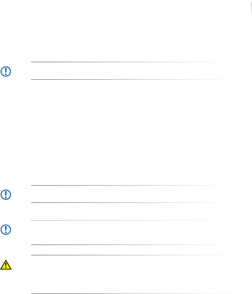
The following schematic is an example of the interface connection
for a ST1 transport configuration.
SMEMA connections: S6056 ST1
NOTICE
The connections have to be adjusted depending on the transport
system configuration.
n-1n+1
Infeed direction
n-1A n+1A
n-1A
n+1A
Installation
Integrating the inspection system into the line
89
Inspection system X7056 | Operating manual |
Version 3.1 Rev.006| 2016-01-06 | 30.009.1930a
Connecting
SMEMA/SV70
ATTENTION
Material damage
Connection must only be done by qualified personnel.
Perform the following work steps:
Connect the adjacent transport conveyors to the SMEMA/SV70
connection plugs according to the shown connection schematic
and configuration of the transport system, see section „Product
description“ > „Overview“ (Page 48).
SMEMA/SV70 is connected.
Linking the
inspection
system via
Interlock
ATTENTION
Material damage
Connection must only be done by qualified personnel.
ATTENTION
Operation malfunctions
Open Interlock connections can cause the system to stop.
The Interlock linkage connections must be plugged in.
DANGER
Confusion with safety circuit
The interlock connection does not meet the criteria of a safety
circuit connection!
The connections of the Interlock link may only be used to link
adjacent devices.
Perform the following work steps:
Connect the adjacent transport conveyors or systems to the
Interlock connection, see „Product description“ > „Interlock
linkage“ (Page 49).
The inspection system is linked via the Interlock.
Network connection
This section contains information about the network connection.
This section contains:
Information about the network connection
Connecting network