X service技术参数 - 第11页
11 Placement Heads 20-Noz zle Coll ect & Place Head fo r Very High-Speed Placem ent Description The 20-nozzle Collect & Place head works on the Collect & Place principle. Thi s means that, w ithin each cy cle…
10
Placement Heads
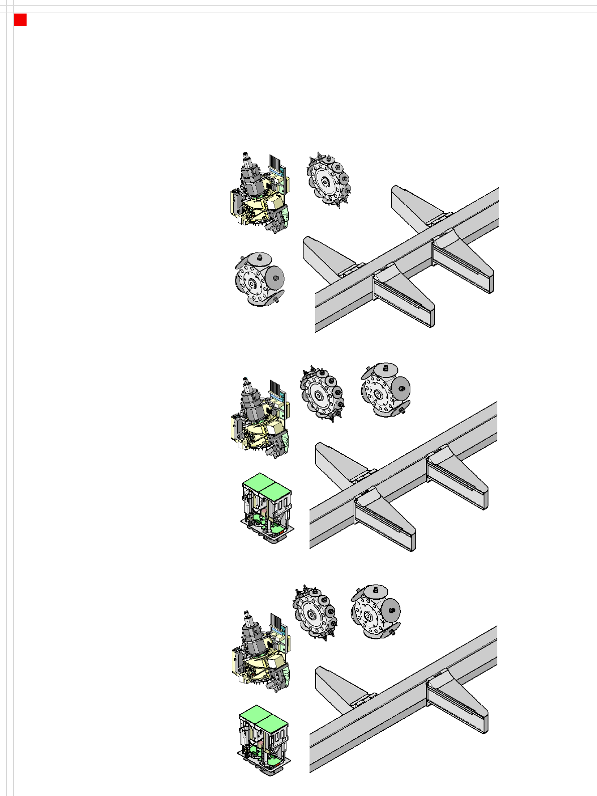
Head Modularity
Description
SIPLACE X machines are char-
acterized by their excellent
flexibility in the production
process. This flexibility is
partly due to the head mod-
ularity. Different placement
head variants can be config-
ured to suit the production
requirements. The illustra-
tions show the placement
head variants for the SIPLACE
X2, X3 and X4 machines.
Section "Machine Description
- Technical Data - “ from page
5 contains a list of placement
head configurations and
placement rates.
There is also a reconfigura-
tion kit if you wish to change
the placement head locally.
This package contains the
appropriate nozzle changers,
assembly parts, cables, etc, in
addition to the placement
head.
C&P12
C&P6
Placement area 2
G1
G2
G3
G4
C&P20/C&P12/C&P6
C&P20/C&P12/C&P6
C&P20/C&P12/C&P6
C&P20/C&P12/C&P6
C&P20
Placement area 1
SIPLACE X4
SIPLACE X3
TH
C&P12
Placement area 2
G1
G3
G4
C&P20/C&P12/C&P6/TH
C&P20/C&P12/C&P6
C&P20/C&P12/C&P6
C&P6
Placement area 1
C&P20
SIPLACE X2
TH
C&P12
Placement area 2
G1
G3
C&P20/C&P12/C&P6/TH
C&P20/C&P12/C&P6/TH
C&P6
Placement area 1
C&P20
11
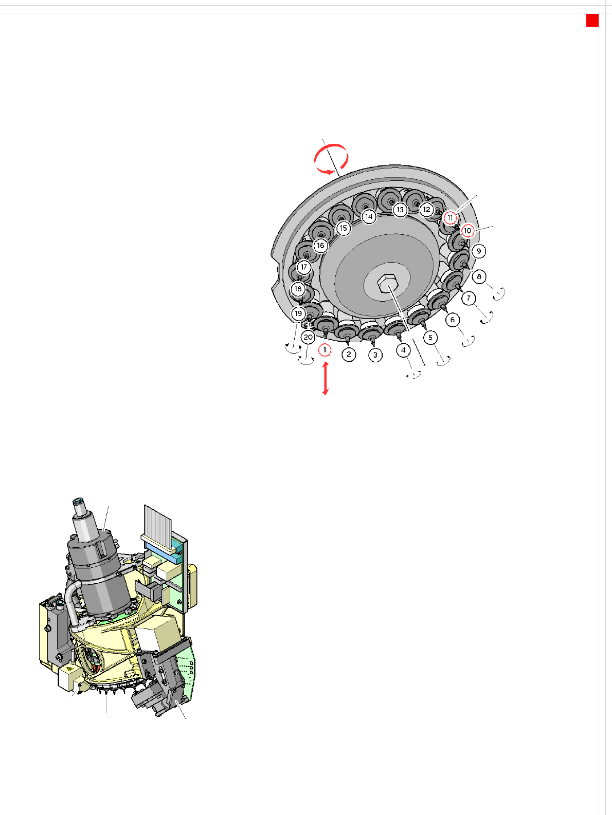
Placement Heads
20-Nozzle Collect&Place Head for
Very High-Speed Placement
Description
The 20-nozzle Collect & Place
head works on the Collect &
Place principle. This means
that, within each cycle,
twenty components are
picked up by the placement
head, are optically centered
on the way to the board and
are rotated into the required
placement angle. Lastly, the
component is placed gently
and accurately on the board.
The 20-nozzle Collect & Place
head succeeds in consider-
ably increasing the output of
the placement head and
thus of the overall place-
ment machine. The high-res-
olution component camera
allows the 20-nozzle Collect
& Place head to optically cen-
ter and place component
sizes ranging from 0201 to 6
x 6 mm².
Checking and self-learning
functions
The reliability of the Collect &
Place head is increased by
various checking and self-
learning functions.
• A component sensor is in-
stalled on the 20-nozzle
Collect & Place head to in-
crease the placement reli-
ability. It checks for the
presence of a component
at the nozzle at the pick-up
and placement position.
• The digital component
camera on the placement
head determines the pack-
age form and the precise
position of each compo-
nent at the nozzle. Any
deviations from the re-
quired pick-up position are
corrected before place-
ment takes place.
• A sensor registers the rela-
tive movement between
nozzle and segment while
setting down compo-
nents, and sends a signal
to the axis controller to
regulate the position. With
this sensor stop method,
differences in height dur-
ing pick-up and any un-
evenness of the PCB
surface are compensated
during placement.
Star
rotation
Pick up compo-
nent and place it
Turn component
individually
Optically center
component
Check
vacuum
Component
sensor
Component
sensor
Star motor
Star with
20 nozzles
Component
camera
12
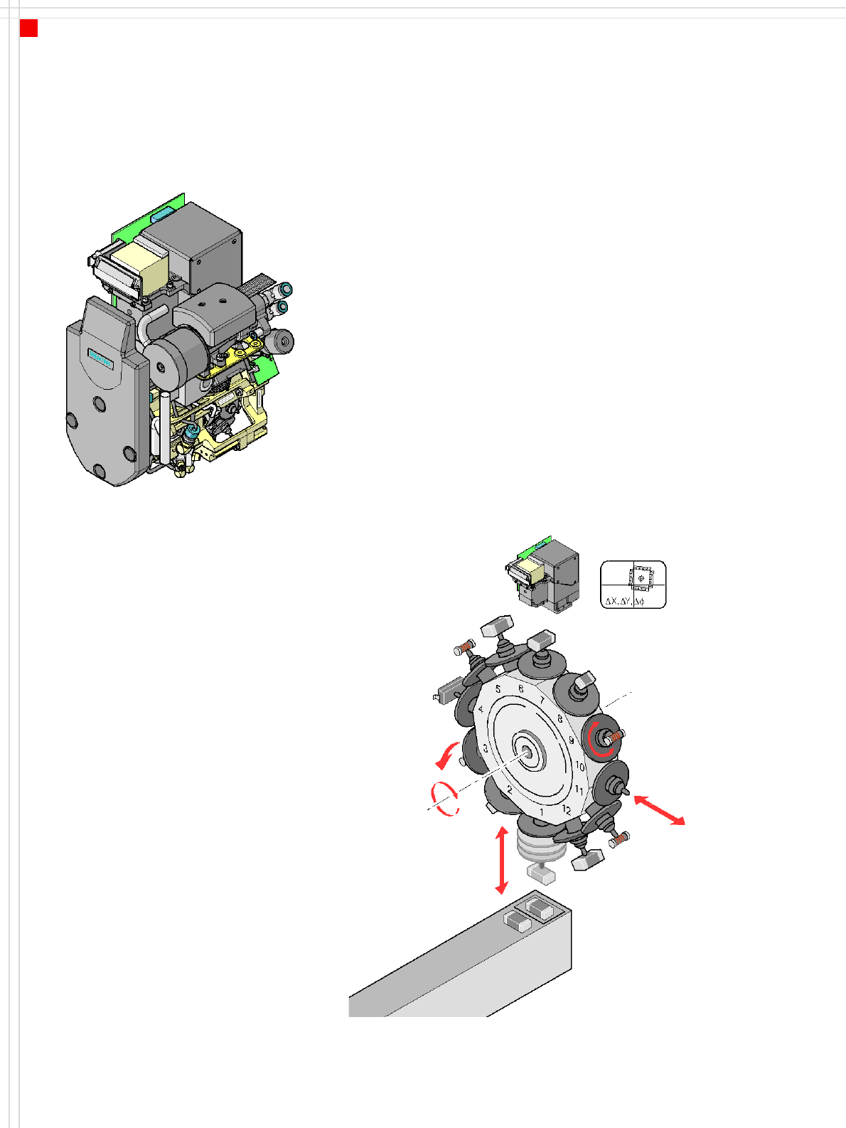
Placement Heads
12-Nozzle Collect & Place Head for
High-Speed Placement
Description
The 12-nozzle Collect & Place
head works on the Collect &
Place principle. This means
that, within each cycle,
twelve components are
picked up by the placement
head, are optically centered
on the way to the board and
are rotated into the required
placement angle. Lastly, the
air kiss sets down the compo-
nent gently and accurately
on the board.
Checking and self-learning
functions
The reliability of the Collect &
Place head is increased by
various checking and self-
learning functions.
• For example, vacuum
checks at the nozzles indi-
cate whether the compo-
nent was picked up or set
down correctly.
•A digital component cam-
era on the placement head
determines the precise
position of each compo-
nent at the nozzle. Any de-
viations from the required
pick-up position are cor-
rected before placement
takes place.
• The package form is also
checked and the compo-
nent is not placed if the
geometric data thus deter-
mined differs from the
programmed data.
The vertical axis for picking
up and placing the compo-
nent works in sensor stop
mode, in which differences
in height during pick-up and
any unevenness of the PCB
surface are compensated
during placement.
In addition to the vacuum
check, an optional compo-
nent sensor may be used to
check for the presence of a
component at the nozzle.
The use of a component sen-
sor is recommended, particu-
larly when placing small
components, such as 0201.
"High-resolution camera“
option
The high-resolution compo-
nent camera allows the
12-nozzle Collect & Place
head to optically center and
place component sizes rang-
ing from 0201 to 18.7 x
18.7 mm².
Component vision module
DP axis:
Rotate component
to placement angle
Pull off or
insert sleeve
Z axis
Pick up or
place component
DR axis:
Rotate star
Reject
component