X service技术参数 - 第4页
4 Signal Curve 39 SMEMA Inte rface 40 Connector Assignment 40 Signal Curve 41 Technical Data 42 Electrical Ratings and Compressed Air Supply 42 Electrica l Connec tion, Interfa ces and Com pressed Ai r Connec tion 43 Dim…

3
SIPLACE X-Series
Content
SIPLACE X-Series 3
Content 3
Machine Description 5
Overview 5
Extensions 6
Technical Data 7
Line Concept 9
Description 9
Placement Heads 10
Head Modularity 10
20-Nozzle Collect&Place Head for Very High-Speed Placement 11
12-Nozzle Collect & Place Head for High-Speed Placement 12
6-Nozzle Collect&Place Head for High-Speed IC Placement 13
Collect & Place Heads 14
Technical Data for the C&P Heads 14
TwinHead for High-Precision IC Placement 15
Technical Data for the TwinHead 16
Nozzle Changers (Collect & Place Heads) 17
Nozzle Changer (TwinHead) 18
Technical Data for the Nozzle Changers 19
PCB Conveyor 20
Single Conveyor 20
Technical Data for the Single Conveyor 21
Flexible Dual Conveyor 22
Technical Data for the Dual Conveyor 23
SIPLACE PCB Barcode for Product-Controlled Production (Option) 24
Component Feeding 25
SIPLACE X-Series Component Changeover Table 25
Technical Data 26
Tape Feeder Modules, X-Series 27
S Tape Feeder Modules 28
Bulk Case and Vibratory Stick Feeder Modules for the SIPLACE HF CO Changeover Table 29
Dummy Feeder Modules 30
Manual Trays 31
Matrix Tray Changer 32
Technical Data 33
Vision Sensor Technology 35
PCB Position Recognition 35
Bad Board Recognition 37
Position Recognition for Feeder Modules 37
Technical Data 38
Siemens Signal Interface 38
Connector Assignment 38

4
Signal Curve 39
SMEMA Interface 40
Connector Assignment 40
Signal Curve 41
Technical Data 42
Electrical Ratings and Compressed Air Supply 42
Electrical Connection, Interfaces and Compressed Air Connection 43
Dimensions and Set-up Conditions 44
Placement System’s Center of Gravity 45
Maneuvering Radii 46
MTC Dimensions and Set-Up Conditions 46
Transport and Delivery Configuration 47
Sample Configuration 48
Option List for the SIPLACE X-Series 49
SIPLACE X-Series
Content
5
Machine Description
Overview
Description
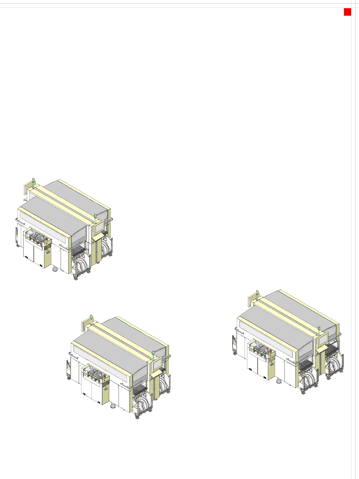
Three variants of the SIPLACE
X-series placement machines
are available:
SIPLACE X2, the placement
machine with 2 gantries,
SIPLACE X3, the placement
machine with 3 gantries and
SIPLACE X4, the placement
machine with 4 gantries
Two placement methods are
used:
•the Collect&Place
method for high-speed
placement of standard
components (see illustra-
tion on page 6)
•the Pick&Place method
for fast placement of spe-
cial fine-pitch and super-
fine pitch components
The gantries driven by linear
motors can be positioned
quickly and accurately in the
X and Y directions. There is a
placement head on each gan-
try.
The head modularity princi-
ple allows the placement
heads to be reconfigured to
suit changing requirements.
Table "Technical Data“ on
page 7 contains a list of the
possible placement head
configurations and the
resulting placement rate.
The moving head picks up
the components from their
stationary feeder, and places
them on the PCB, which is
also stationary. This proven
SIPLACE principle has many
advantages:
• Short down times for refill-
ing or splicing
• Even the smallest compo-
nents are picked up reli-
ably
• The components cannot
slip on the PCB
• Minimal traversing paths
High flexibility, cost-effec-
tiveness and set-up reliability
guarantee that the SIPLACE X
placement systems will be
highly productive. The mini-
mal down times increase
utilization, thus further
increasing productivity.
SIPLACE X2
SIPLACE X3
SIPLACE X4