X service技术参数 - 第5页
5 Machine Description Overview Description Three vari ants of the SIPLACE X-series placement m achines are available : SIPLACE X2, the placement machine with 2 ga ntries, SIPLACE X3, the placement machine with 3 gantries…

4
Signal Curve 39
SMEMA Interface 40
Connector Assignment 40
Signal Curve 41
Technical Data 42
Electrical Ratings and Compressed Air Supply 42
Electrical Connection, Interfaces and Compressed Air Connection 43
Dimensions and Set-up Conditions 44
Placement System’s Center of Gravity 45
Maneuvering Radii 46
MTC Dimensions and Set-Up Conditions 46
Transport and Delivery Configuration 47
Sample Configuration 48
Option List for the SIPLACE X-Series 49
SIPLACE X-Series
Content
5
Machine Description
Overview
Description
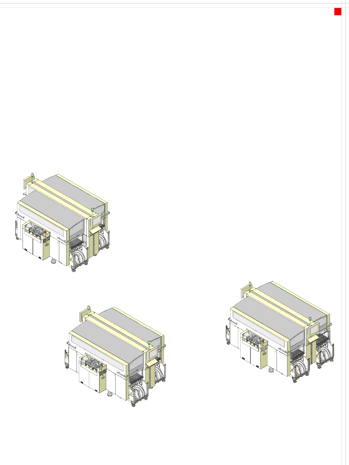
Three variants of the SIPLACE
X-series placement machines
are available:
SIPLACE X2, the placement
machine with 2 gantries,
SIPLACE X3, the placement
machine with 3 gantries and
SIPLACE X4, the placement
machine with 4 gantries
Two placement methods are
used:
•the Collect&Place
method for high-speed
placement of standard
components (see illustra-
tion on page 6)
•the Pick&Place method
for fast placement of spe-
cial fine-pitch and super-
fine pitch components
The gantries driven by linear
motors can be positioned
quickly and accurately in the
X and Y directions. There is a
placement head on each gan-
try.
The head modularity princi-
ple allows the placement
heads to be reconfigured to
suit changing requirements.
Table "Technical Data“ on
page 7 contains a list of the
possible placement head
configurations and the
resulting placement rate.
The moving head picks up
the components from their
stationary feeder, and places
them on the PCB, which is
also stationary. This proven
SIPLACE principle has many
advantages:
• Short down times for refill-
ing or splicing
• Even the smallest compo-
nents are picked up reli-
ably
• The components cannot
slip on the PCB
• Minimal traversing paths
High flexibility, cost-effec-
tiveness and set-up reliability
guarantee that the SIPLACE X
placement systems will be
highly productive. The mini-
mal down times increase
utilization, thus further
increasing productivity.
SIPLACE X2
SIPLACE X3
SIPLACE X4
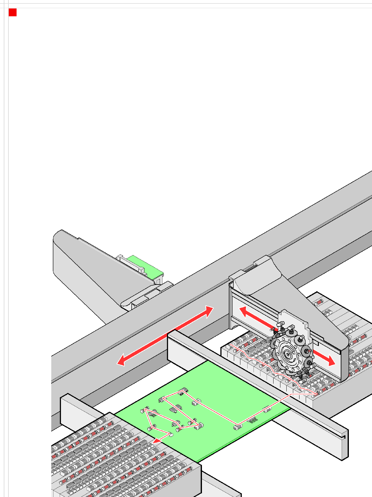
6
Placement principle
Collect&Place
Machine Description
Extensions
Extensions
The following options are
available to extend the
machine's functionality:
• Additional component
changeover tables
increase machine utiliza-
tion since set-up times can
be reduced by carrying out
preliminary set-up off the
machine.
• Large and sensitive fine-
pitch components can be
supplied in trays by a
matrix tray changer.
• The dual conveyor also
increases machine utiliza-
tion by eliminating non-
productive PCB transport
times.
• Automatic nozzle chang-
ers speed up and optimize
the nozzle configuration
process.
• PCB barcode scanners
allow the production set-
up to be changed over
when triggered by a new
product.
• Component barcode scan-
ners optimize the set-up
and refill checks.
• The productivity lift imple-
ments the concept of par-
allel placement, and thus
improves the ratio be-
tween productive and
non-productive times.