X service技术参数 - 第8页
8 Machine Description Technical Data *) The HF-series component ch angeover table and feeder modules canno t be used together with t he 20-nozzle Collect & Place h ead. Component heigh t C&P20: 4 mm (larger heigh…

7
Machine Description
Technical Data
Types of placement head 20-nozzle Collect & Place head (C&P20)
12-nozzle Collect & Place head (C&P12)
6-nozzle Collect & Place head (C&P6)
SIPLACE TwinHead (TH)
SIPLACE X4 placement system
Number of gantries 4 (see Fig. page 10)
Placement head configuration
and placement rate
(Benchmark test)
Placement area 1 Placement area 2 Placement rate
C&P20 / C&P20 C&P20 / C&P20 80.000 cph
C&P20 / C&P20 C&P12 / C&P12 66.400 cph
C&P20 / C&P20 C&P12 / C&P6 60.300 cph
C&P20 / C&P20 C&P6 / C&P6 58.300 cph
C&P12 / C&P12 C&P12 / C&P12 52.800 cph
C&P12 / C&P12 C&P12 / C&P6 46.700 cph
C&P12 / C&P12 C&P6 / C&P6 44.700 cph
C&P12 / C&P6 C&P12 / C&P6 40.600 cph
C&P12 / C&P6 C&P6 / C&P6 38.600 cph
C&P6 / C&P6 C&P6 / C&P6 36.600 cph
SIPLACE X3 placement system
Number of gantries 3 (see Fig. page 10)
Placement head configuration
and placement rate
(Benchmark test)
Placement area 1 Placement area 2 Placement rate
C&P20 / C&P20 C&P20
*)
60.000 cph
C&P20 / C&P20 C&P12 54.000 cph
C&P20 / C&P20 C&P6 49.300 cph
C&P20 / C&P20 TH 43.700 cph
C&P12 / C&P12 C&P12 40.400 cph
C&P12 / C&P12 C&P6 35.700 cph
C&P12 / C&P12 cph 30.100 cph
C&P12 / C&P6 C&P6 29.600 cph
C&P12 / C&P6 TH 24.000 cph
C&P6 / C&P6 C&P6 27.600 cph
C&P6 / C&P6 TH 22.000 cph
*) This combination is only available on request
SIPLACE X2 placement system
Number of gantries 2 (see Fig. page 10)
Placement head configuration
and placement rate
(Benchmark test)
Placement area 1 Placement area 2 Placement rate
C&P20 C&P20
*)
40.000 cph
C&P20 C&P12
*)
34.000 cph
C&P20 C&P6
*)
29.300 cph
C&P20 TH
*)
23.700 cph
C&P12 C&P12 28.000 cph
C&P12 C&P6 23.300 cph
C&P12 TH 17.700 cph
C&P6 C&P6 18.600 cph
C&P6 TH 13.000 cph
TH TH 7.400 cph
*) This combination is only available on request
Placement positions 3.500 / gantry for the Collect & Place head
Range of components 0.6 x 0.3 mm² (0201)
**)
to 85 x 85 mm² / 125 x 10 mm² max. 200 x
125 mm² (with restrictions)
**) Smaller components, e.g. 01005 available on request

8
Machine Description
Technical Data
*) The HF-series component changeover table and feeder modules cannot be used together with the
20-nozzle Collect & Place head.
Component height C&P20: 4 mm (larger heights on request)
C&P12: 6 mm (larger heights on request)
C&P6: 8.5 mm (larger heights on request)
TH: 25 mm (larger heights on request)
Placement accuracy / angular accuracy C&P20: ± 41 µm, ± 0.5° / (3σ), ± 55 µm, ± 0.7° / (4σ)
C&P12: ± 45 µm, ± 0.5° / (3σ), ± 60 µm, ± 0.7° / (4σ)
C&P12: ± 41 µm, ± 0.5° / (3 σ), ± 55 µm, ± 0.7° / (4 σ) (high-res. camera)
C&P6: ± 45 µm, ± 0.2° / (3σ), ± 60 µm, ± 0.3° / (4σ)
TH: ± 26 µm, ± 0.05° / (3σ), ± 35 µm, ± 0.07° / (4σ) (fine-pitch camera)
± 22 µm, ± 0.05° / (3σ), ± 30 µm, ± 0.07° / (4σ) (flip-chip camera)
Component Feeding
(SIPLACE X-series component
changeover table)
4 component changeover tables with tape reel holders and integral waste
containers
40 x 8 mm feeder module locations per CO changeover table or matrix tray
changer in place of CO changeover tables, X2: 2 MTC2, X3: 1 MTC2
Feeder module types (X-series) Component tapes
Feeding capacity
(SIPLACE X-series component
changeover table)
160 8 mm X feeder modules
80 12 mm X feeder modules
64 16 mm X feeder modules
64 24 mm X feeder modules
40 32 mm X feeder modules
32 44 mm X feeder modules
24 56 mm X feeder modules
20 72 mm X feeder modules
16 88 mm X feeder modules
Component Feeding
(HF-series component
changeover table
*
)
4 component changeover tables with tape reel holders and integral waste
containers
15 slots, 30 mm wide per changeover table or matrix tray changer, rather
than component changeover tables, X2: 2 MTC2, X3: 1 MTC2
Feeder module types
(HF-series
*
)
Tapes, bulk cases, stick magazines, application-specific OEM feeder mod-
ules, surftape feeder modules (8, 12, 16 mm), manual trays
Feeding capacity
(HF-series component
changeover table
*
)
60 tape feeder modules 3 x 8 mm S (180 tracks)
60 tape feeder modules 2 x 8 mm S (120 tracks)
60 tape feeder modules 12/16 mm S
40 tape feeder modules 24/32 mm S
28 tape feeder modules 44 mm S
24 tape feeder modules 56 mm S
20 tape feeder modules 72 mm S
16 tape feeder modules 88 mm S
PCB format
(LxW)
PLEASE NOTE:
With PCB widths > 450 mm make sure
that the peripheral modules are also
able to process these widths.
Single Conveyor
50 x 50 mm² to 450 x 508 mm²
50 x 80 mm² to 610 x 508 mm² ("Long board" option)
Dual conveyor
50 x 50 mm² to 450 x 250 mm²
50 x 80 mm² to 610 x 250 mm² ("Long board" option)
Dual conveyor in Single conveyor mode
50 x 50 mm² to 450 x 450 mm²
50 x 80 mm² to 610 x 450 mm² ("Long board" option)
PCB thickness 0.3 - 4.5 mm (thicker PCBs on request)
Dimensions of the placement systems see figure page 45
9
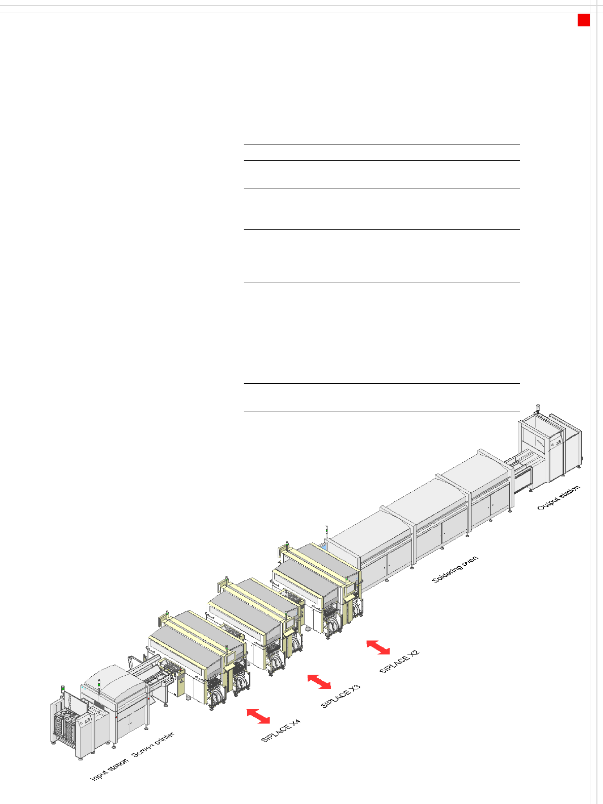
Line Concept
Description
Description
SIPLACE X machines allow a
production line to be individ-
ually configured from a range
of identical and different
modules. As the production
requirements change, the
individual placement
system - which are both mod-
ular and compact - can be
quickly recombined without
great effort.
The SIPLACE X family has ex-
actly the right placement sys-
tem, whatever the output
requirements:
SIPLACE X placement
systems cover the SMD spec-
trum of components from
0201 to 125 x 10 mm² with a
high placement rate.
SIPLACE set-up optimiza-
tion is a tool for increasing
the line's productivity.
The software calculates indi-
vidual set-ups for individual
products, individual set-ups
for different products and
family set-ups for different
products.
The program data can be
exchanged between the indi-
vidual lines - even for
different machine configura-
tions.
System SIPLACE SMD placement lines
Placement
modules
SIPLACE X2, X3 or X4
Peripheral
modules
Input/output stations, screen printers,
soldering ovens, inspection stations, etc,
available from Siemens L&A
Component
range
0201 to 85 x 85 mm² / 125 x 10 mm² max.
200 x 125 mm² (with restrictions). The
range of components depends on which
head configuration is selected.
PCB conveyor Single and dual conveyor with automatic
width adjustment unit;
Dual conveyor in Single conveyor mode;
"Wide board“ mode, "Long board" option
and combinations thereof for both PCB
conveyors. The maximum PCB width is
determined by the module with the small-
est PCB conveyor width.
Space
required
6.0 m² for the X2 module,
6.7 m² per X3 or X4 module