AOI_RS_v85_en - 第103页
Chap ter3 SPC User Ma nual AOI Repair Station 99 monitor statistics data and control display area as explained below . 7.3.1 Function menu area: This area lists all the functions of this software. Based on the functional…
Chapter3 SPC User Manual
AOI Repair Station
98
7 X Bar R Chart
7.1 Setting
Select [Utility/ Inline Component Data Output to SPC] in AOI main
program.
Set [Setting/Defect Warning/ Output7100XY] as [True] in Ptril.exe
program on Repair Station PC.
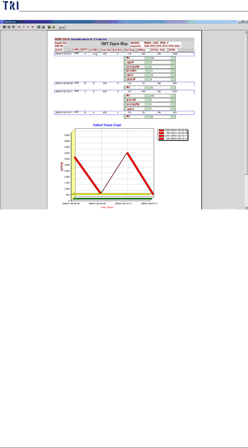
7.2 Objective
This function shows the stability and capability of the process for
reference by the operator in deciding whether or not to adjust the
process or machine. In addition, it includes error management
parameter setting so that once the data in the control chart hits the error
parameters, the system automatically sends out an alarm. Currently,
this software is applicable to these two types of test machines: TR7006
and TR7100. This document will explain how to use this software
package. The following figure shows the main menu of this function.
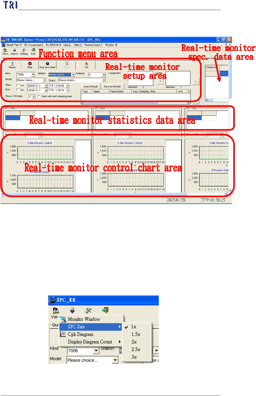
7.3 Explanation - Main Frame
The main menu can be divided into the Function menu area, Real-time
monitor setup area, Real-time monitor spec. data area and Real-time
Chapter3 SPC User Manual
AOI Repair Station
99
monitor statistics data and control display area as explained below.
7.3.1 Function menu area: This area lists all the functions of this software.
Based on the functional properties, these functions are grouped into 3
types, namely, View, Alarm and Setting, as explained below.
7.3.1.1 View
ww
w:
::
: Functions under this category are used to “view” data.
Currently there are two functions: SPC Size and Monitor Window.
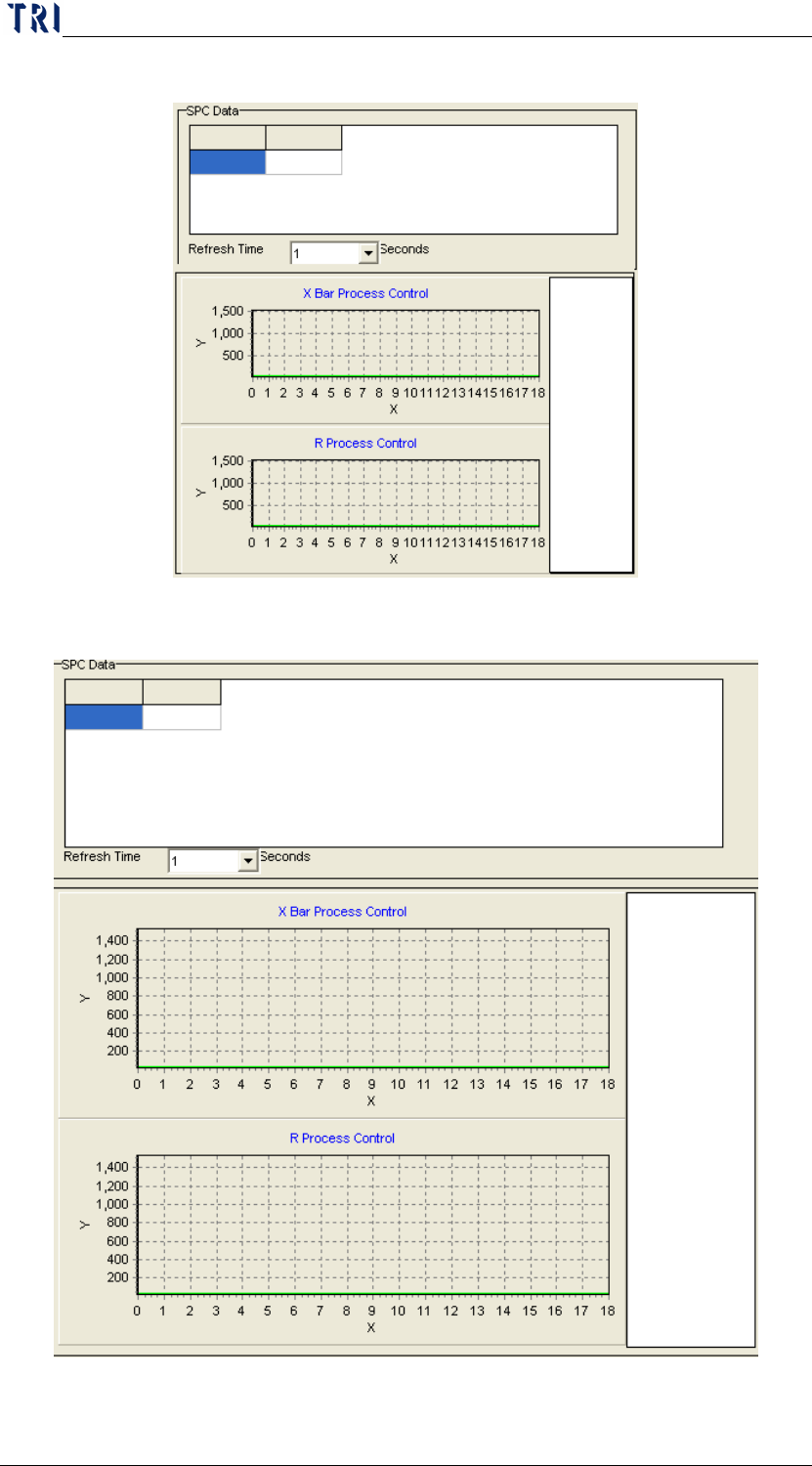
SPC Size: This function allows you to change the SPC size
anytime before, during or after monitoring as shown in the figure
below.
a. 1x: Restores the control chart to its original size as shown in
Chapter3 SPC User Manual
AOI Repair Station
100
the following figure.
b. 1.5x: Zooms the control chart to 1.5 times its original size.