AOI_RS_v85_en - 第141页
Chap ter3 SPC User Ma nual AOI Repair Station 137 When user enables the S tyle 3 Report and clicks o n [Go!], system will start the reporting function. S ystem cha nges the date in [Start] and [End] field to that day; …
Chapter3 SPC User Manual
AOI Repair Station
136
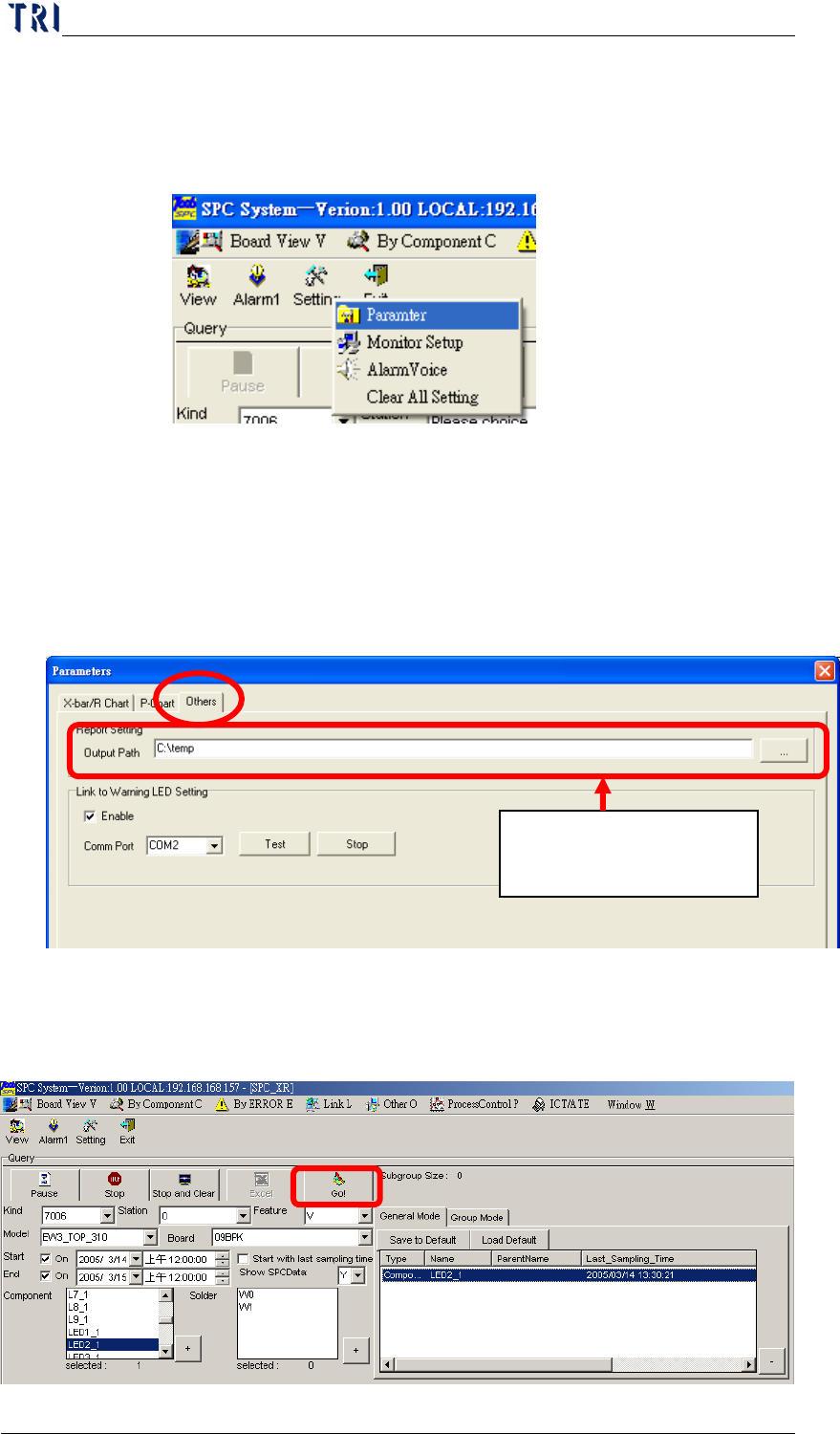
7.4.1.10 Other Settings
Besides the 8 settings mentioned above, there are several other
settings. You can press “Parameter” in “Setting” ,then select
“Others” page.
Report Setting: Select the default path for outputting report.
Link to Warning LED Setting: If check “Enable” item, user can set
a signal tower to display warning when there is an alarm coming up.
“Comm Prot” means the communication port (COM1, COM2…)
the signal tower uses; “Test” and “Stop” is to test the signal tower
and to stop testing.
7.4.2
Start monitoring
After completing all settings, just click on the “Go!” button and the
system will starts monitoring as shown in the following figure.
Select the default path
for outputting report
Chapter3 SPC User Manual
AOI Repair Station
137
When user enables the Style 3 Report and clicks on [Go!], system
will start the reporting function. System changes the date in [Start]
and [End] field to that day; it also changes the time in [Start] and
[End] field to the reporting time set in [ReportData_Interval]; and
the check boxes front of [Start] and [End] are checked
automatically. When time for reporting, system will report Style
3 Report and change the date in [Start] and [End] field to the next
day. The function goes this way until a user Pause or Stop the
monitoring.
7.4.3
Monitoring
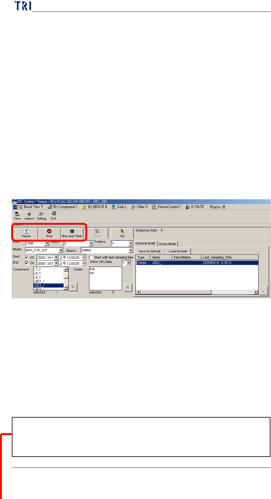
(I) During monitoring, you can perform these three actions:
①
Click on “Pause” to halt monitoring
②
Click on “Stop” to stop monitoring
③
Click on “Stop and Clear” to stop monitoring and clear all data in
the screen.
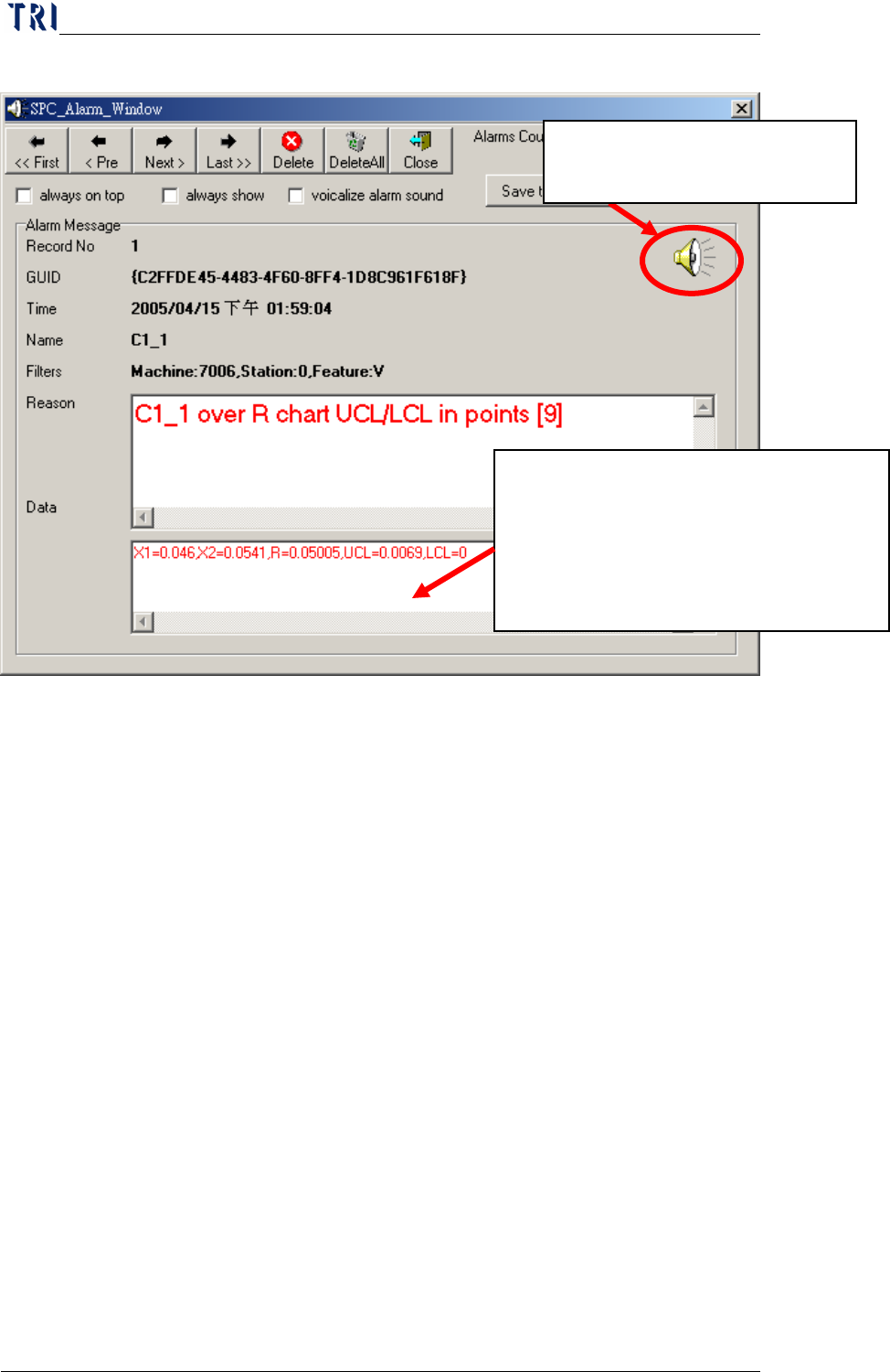
In addition, after each sampling the system will check if this
component or solder is an applicable monitor item (that is,
non-realtime monitor item) for this alarm. Real-time monitor items
will definitely use this alarm. If applicable, the system will check for
errors by comparing the alarm conditions with the computed control
upper limit, lower limit, and control mean value and sample mean
value. If there is an error, the system will generate beeps to remind
the user that error has occurred and also display the following alarm
window.
The “Reason” box shows what kind of error occurred in a component while “in points” at the end
of reason text line also indicates the error control point location. Using this figure as example,
“C1_1” has an “over X bar chart UCL/LCL” error at point “9”.
Chapter3 SPC User Manual
AOI Repair Station
138
The description for the entire screen is as follows:
The task bar on top is used for alarm message operation. The “<<
First” button allows you skip to the first alarm message. Click
on “< Pre” to go back to the previous alarm message or click on
“Next >” to go to the next alarm message. The “Last >>” button
allows you skip to the last alarm message. Use “Delete” to
delete the current alarm message and use “DeleteAll” to delete
all alarm messages. Use “Close” to close this message window.
The current message count is displayed to the right of the task
bar.
The “always on top” option below the task bar indicates that this
window is displayed on the topmost layer. If this item is
checked (
√), then the system will display this window on the
topmost layer and it will not be overlapped by other windows.
The “always show” option indicates whether or not to pop up this
window automatically. If this item is checked (√), then the
system will automatically open this window when an error occurs.
The “vocalize alarm sound” indicates whether or not to generate
beeps when an error occurs. If this item is checked (
√), then the
ndicates that at the time the error occurs, the
X1~X5 data used are the sample value, average is
the mean value, UCL is the upper control limit,
and LCL is the lower control limit.
Note! The
information here varies with the error type.
Click on this icon to open the
window of Alarm Voice Setting.