AOI_RS_v85_en - 第145页
Chap ter3 SPC User Ma nual AOI Repair Station 141 Besides, user can use [V iew Relation Boards Data] to display the data of former and the later few boards of the abnormal data. User sets the number of boards he wants …
Chapter3 SPC User Manual
AOI Repair Station
140
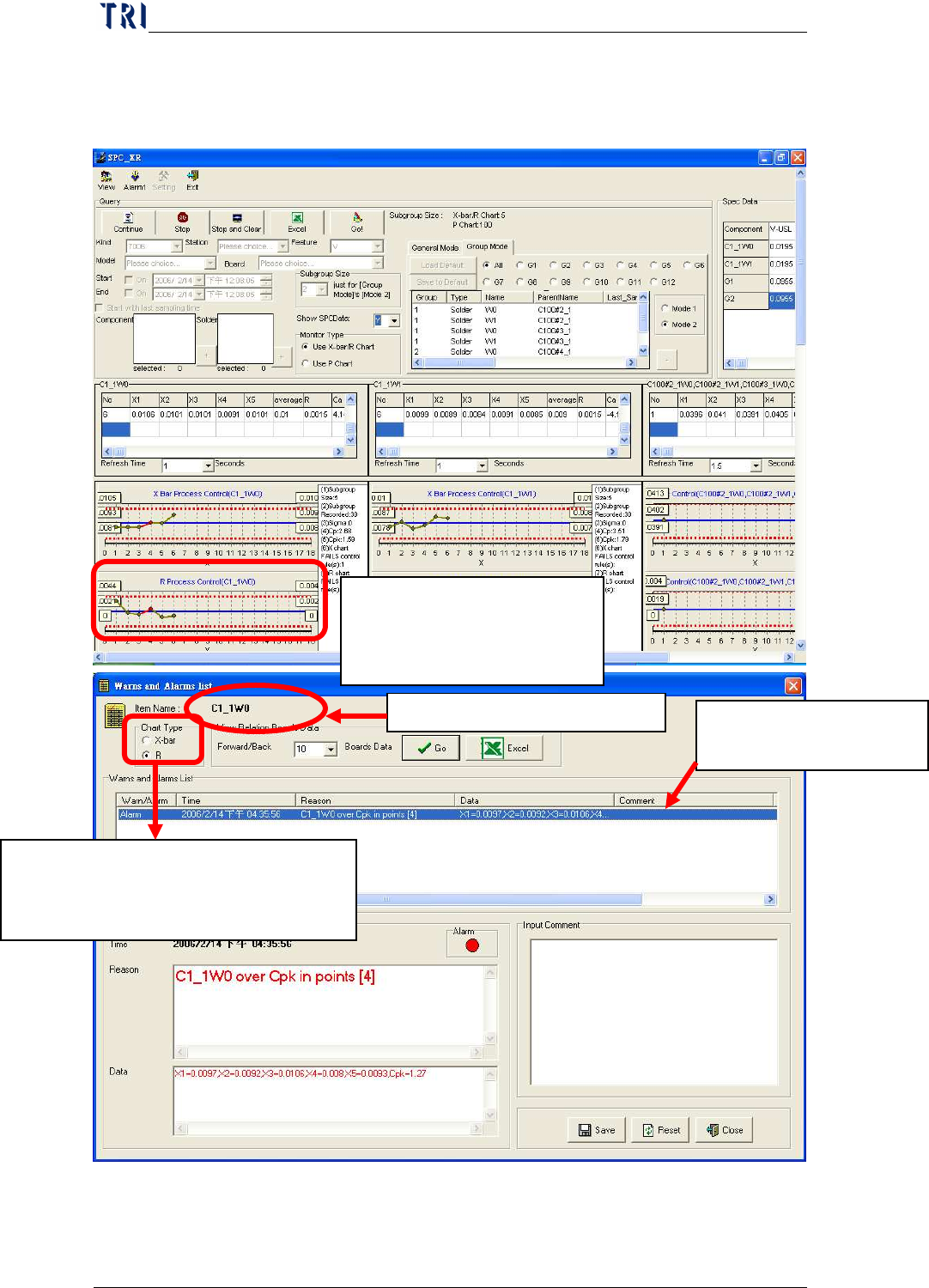
display all error information and open a “Comment” field to input user
remarks as described below:
When error point occurs in
the control chart, click on it
to display the screen below.
Current display chart types. Click on
chart type you want to view:
X
-
bar: X
-
bar chart; R: R Chart
Name of control chart monitor item
Display all error information
for this control chart
Chapter3 SPC User Manual
AOI Repair Station
141
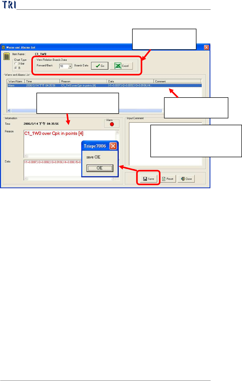
Besides, user can use [View Relation Boards Data] to display the data
of former and the later few boards of the abnormal data. User sets the
number of boards he wants to review then press [Go] to show the other
window to review the data of relating boards, as the window shown
below. Or user can press [Excel] to output excel file directly.
Click on the abnormal
data to review.
Display detailed information
of alarm you selected.
You can key in the remarks for this
alarm data for future tracking. Click
on Save after keying in.
Click on the alarm data you
want to view
Chapter3 SPC User Manual
AOI Repair Station
142
If user has enabled the “Link to Warning LED” function, system will
display this warning window and the signal tower linked to PC will
alarm and light up. User could press [OK] to stop the voice and
lighting.
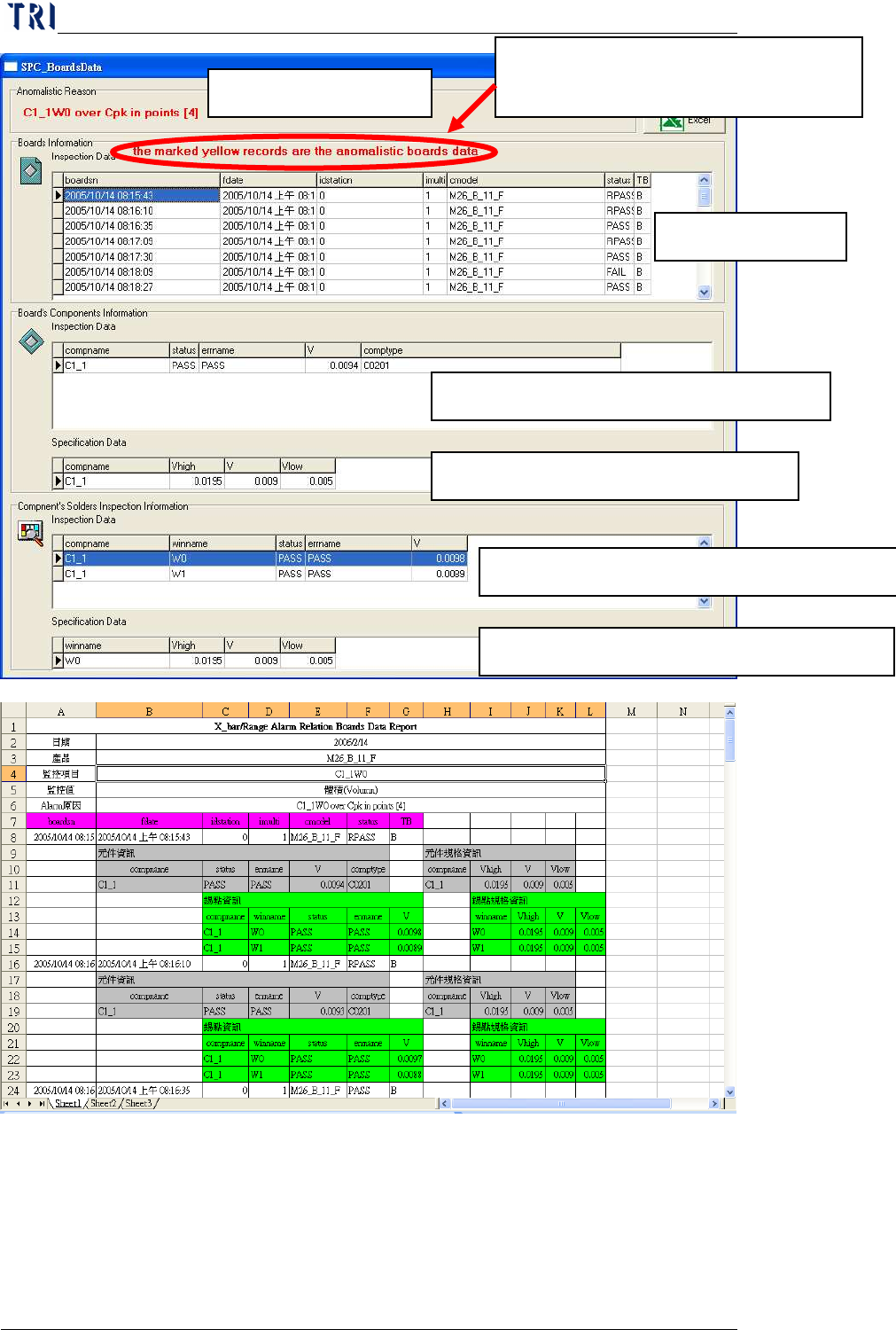
Cause for unusual case
Board Information
Select component information of the board.
The specs of the selected component.
The p
ads information of the selected component.
The specs of the selected pads.
In board information, the data marked
in yellow means abnormal data.