AOI_RS_v85_en - 第77页
Chapter 2 Repair Station Main Progr am AOI Repair Station 73 Define the colors of location frame and line on FOV image. 10.6.7.10 The Color of Board Status Define the colors of all inspection result status. 10.6.7.11…
Chapter 2 Repair Station Main Program
AOI Repair Station
72
SIEM_Mode1: This is the first model to link to Siemens Placer.
Repair Station receives the placer file from AOI machine and the
[Placer File Path] has to be set as [C:\AOI_Repair_data\Placer].
The standard format in [Placement] field in AOI Machine is
[$MMachine$GGantry$FFeeder].
SIEM_Mode2: This is the second model to link to Siemens Placer.
This way is to take the NC files.
10.6.7.7 Placer File Path-Specify the path to save the placer
information.
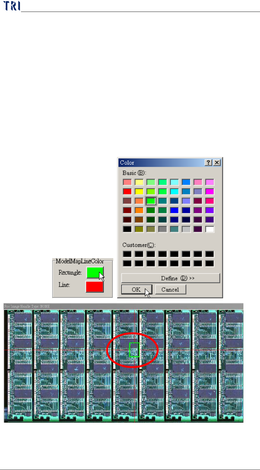
10.6.7.8 Model Map Line Color
Define the colors of location frame and line on panel map.
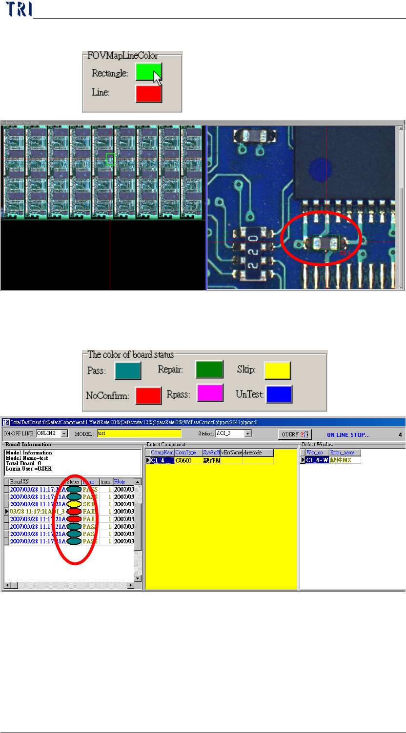
10.6.7.9 FOV Map Line Color
Chapter 2 Repair Station Main Program
AOI Repair Station
73
Define the colors of location frame and line on FOV image.
10.6.7.10 The Color of Board Status
Define the colors of all inspection result status.
10.6.7.11 Generate Defect Map (D:\AoiMap)
When there is a data confirmed as a FAIL board, system will save
the FOV image in [D:\AoiMap\Model Name\ “date”] folder.
10.6.7.12 8x8 BMP Show
Chapter 2 Repair Station Main Program
AOI Repair Station
74
During confirming, there is an 8x8 panel map displayed, and the
defect component will be marked; as the following picture.
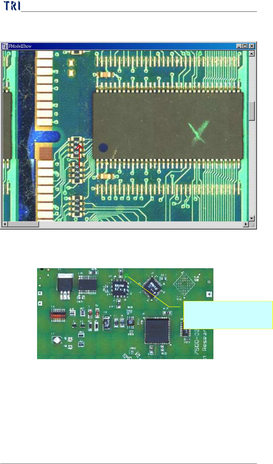
10.6.7.13 Mark Fail in Model Map
System marks the defect on panel map with green box.
10.6.7.14 Repeat Fail、Repeat Times
When the repeat fail count for a component is over the specified
count, system will display a warning.
User has to open [Setting/Other/SPC Output] function also to
cooperate with this function. And user has to double click on
[Board Information/Set SPC Output Date Time] under main frame
Marking the defect with a
green box.