Detailed Circuit Diagram Folder SIPLACE F5.pdf - 第119页
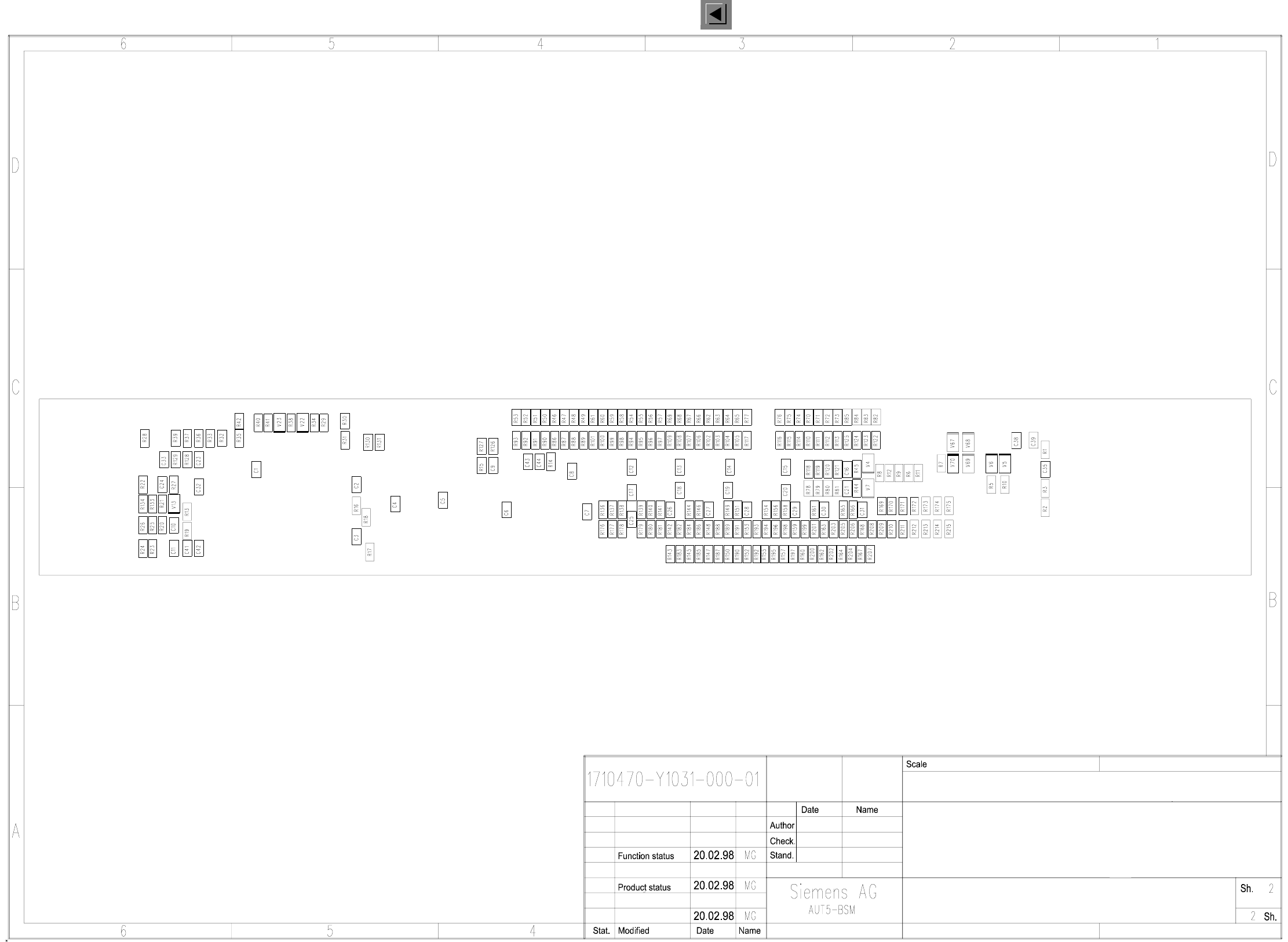
4 Printed Circui t Boards 119 I 0032358 4-010 202ND3 Compo nent ta ble conversion boa rd Compon ent ta ble conv ersion board, SMD SMD placement system Siplace 80 S 003235 84-0 10202ND3
4 Printed Circuit Boards 120
I
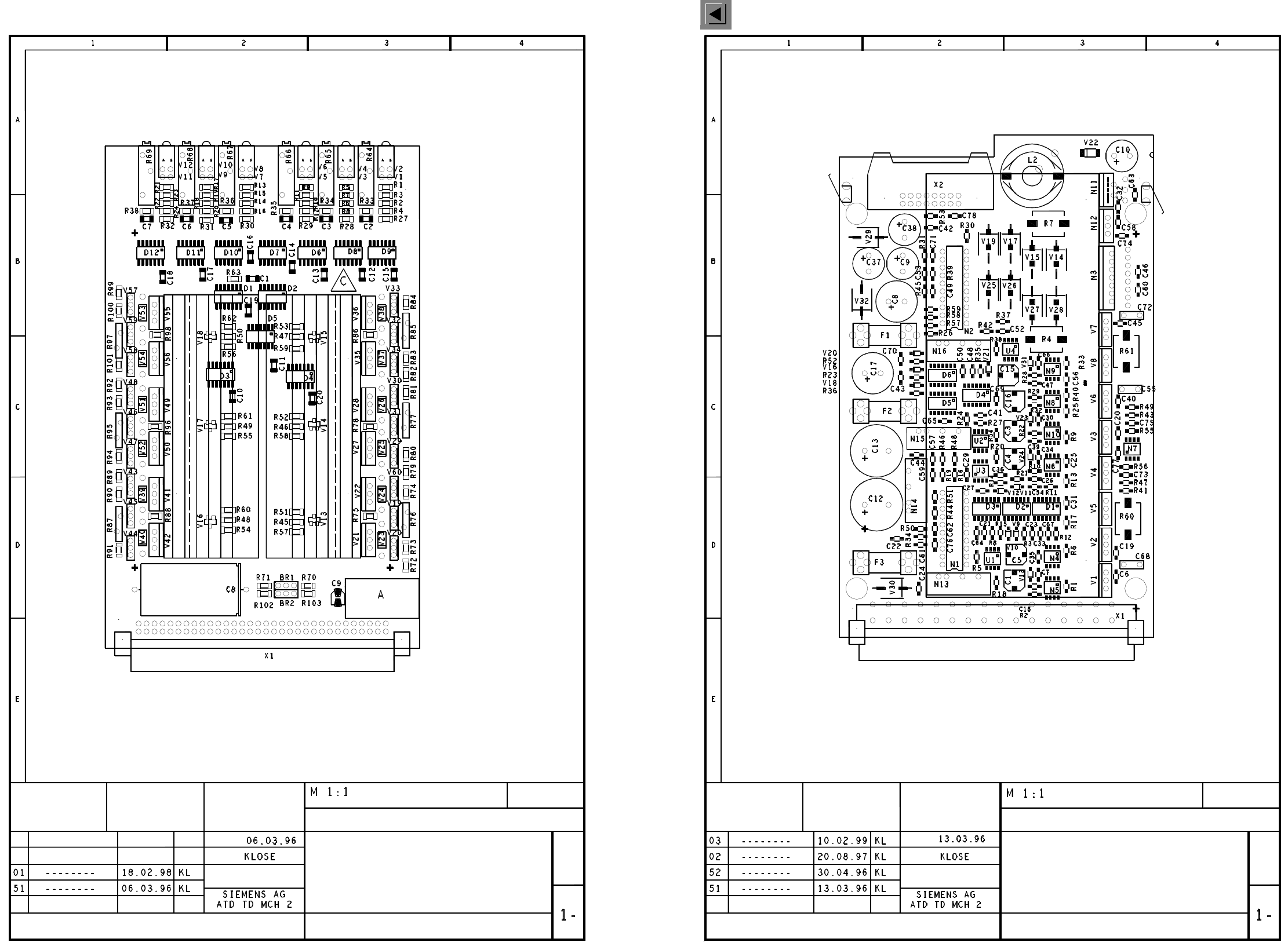
00325460-010101ND4 774 PC board, half bridge board
00325579-020101ND4 775 PC board, step motor control, power unit
Technische Dokumentation Hick, Technische Dokumentation Hick 18.05.00 10:17 00325460-010101ND4.dwg
A = IDENTIFICATION LABEL
B = INSPECTION LABEL
C = ESD LABEL
B = SOLDER SIDE
PCB 774
HALF BRIDGE BOARD
00325460-010101ND4
G32918-H0005-B001-*-0017
COMPONENT MOUNTING DIAGRAM
4-LAYER PCB
Sheet
Stat. Modified Date Name
Date
Name
PCB 775
G32918-H0006-B001-*-0017
00325579-020101ND4
COMPONENT MOUNTING DIAGRAM
4-LAYER PCB
Stat. Modified Date Name
Date
Name
Sheet
Technische Dokumentation Hick, Technische Dokumentation Hick18.05.00 10:16 00325579-020101ND4_LT.dwg
A = IDENTIFICATION LABEL
B = INSPECTION LABEL
C = ESD LABEL
LABELS A, B, C ON PLUG X1
STEP MOTOR CONTROL
POWER CIRCUIT