Detailed Circuit Diagram Folder SIPLACE F5.pdf - 第32页
1 Detailed Circuit Diagr ams 32 I LP03 PCB c onve yor 1, lif t ing t abl e cont rol br GND 10 X8 +24VDC X28 2 3 6 bk br bl lif t ing ta ble 1 bo tt om Sensor switc h, 00326021-xx bk br bl A1 + - ’ d ual conveyor ’ Conver…
1 Detailed Circuit Diagrams 31
I
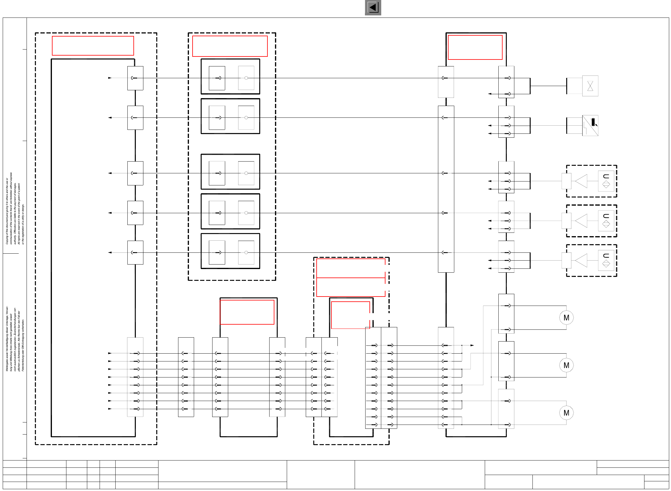
LP02 PCB conveyor 1, conveyor motors control
LP2.DWG
Stromlaufplan/Circuit diagram
PL EA
Hi
18.12.2000
SIEMENS
Sh.
Sh.
SMD Placement System SIPLACE F5
1
1
PCB conveyor 1
Conveyor motors control
X20
2
-wh
+br
6
X22
2
output conveyor 1
00326030-xx
Conveyor motor,
Conveyor motor,
center conveyor 1
00326031-xx
Conveyor motor,
input conveyor 1
00326032-xx
GND
+24VDC
br
bk
bl
GND
6
+24VDC
X36
3
2
br
bk
bl
GND
6
+24VDC
X38
3
2
br
bk
bl
GND
6
+24VDC
X40
3
2
bk
bl
GND
6
X42
2
(Cable)
00327655-xx
X34a
Sonar switch,
00326022-xx
input conveyor 1
00327656-xx
(Cable)
center conveyor 1
Sonar switch,
00326023-xx
X36a
00327657-xx
(Cable)
output conveyor 1
Sonar switch,
00326024-xx
X38a
br
bl -
+
bk A1
stopper 1
00326025-xx
Sensor switch,
11
10
7
8
13,14
1,2,3,4
12
1,2,3,4
13,14
9
8
7
12
11
10
Port A3.4
Port A3.5
Port A3.6
Port A3.7
I/O boards
Port A1.6
Port E1.5
Port E4.6
Port E3.6
Port E4.4
00344266-xx
Terminal panel, left-hand side
Valve ’Extend stopper 1’
Sensor switch ’Stopper 1 retracted’
Sonar switch ’output conveyor 1’
Sonar switch ’center conveyor 1’
Sonar switch ’input conveyor 1’
14
15
16
10
11
12
13
9
X7
19
20
7 X1:4
GND
Output conveyor 1
29a
30b
32b
32a
30a
Input conveyor 1
GND
8
9
10
5
6
7
X2c
board
00325460-xx
X3
13,14
1,2,3,4
X1c
+30VDC switched
Center conveyor 1
X3’
29b
27a
28a
28b
27b
26b
X2sf
Port A3.2
GND
+30VDC switched
Port A3.3
00341851-xx
Control unit
(Cable)
00329283-xx
00326067-xx
(Cable)
6
2
X18
-wh
+br
br
bk
bl
6
3
X34
2
-wh
+br
6
10
12
11
9
8
7
8
10
9
7
6
5
13,14,23,24
1,2,3,4,16,17,18
X6
+30VDC switched
GND
Center conv. 1 ’slow’
Center conv. 1 ’fast’
Output conv. 1 ’slow’
Output conv. 1 ’fast’
Input conv. 1 ’slow’
Input conv. 1 ’fast’
dual conveyor
00325581-xx
Conversion board
halfbridge
6-channel
(Cable)
00331297-xx00321501-xx
(Cable)
X1c
5a
4b
5b
4a
3a
3b
1a/b,2a/b,8a,9a/b
7b/a,12b/a
X4c
1
3
4
5
6
7
8
9
10
13
14
00327615-xx
dual conveyor
Control unit -
Control unit -
single conveyor
00331465-xx
Status Modified Date Name Stand.
Check.
Author
Date
Mat. no.:
CAD file:
Orig./Creat. f./Creat.by
+br
-wh
Valve,
00326026-xx
stopper 1
pk
6
X13
(Cable)
00326068-xx
pk
6
X12
12
8
10
rd-bl
rd
vio
Conversion board
’dual conveyor’
00325581-xx
7
X2ka
11
X2se
11
X1ka
00321497-xx
(Cable)
A1
A1
(Cable)
00321499-xx
10
X4se
10
X1kb
7
X2kb
00326069-xx
(Cable)
A4
(Cable)
00321504-xx
11
X5sf
11
X2kg
7
X6kg
00326069-xx
(Cable)
A3
(Cable)
00321503-xx
11
X4sf
11
X1kf
7
X2kf
00326069-xx
(Cable)
A4
(Cable)
00321504-xx
9
X5sf
9
X2kg
5
X6kg
00326069-xx
(Cable)
9
See page 86
See page 121
See page 92
See page 120
See page 121
See page 65
See page 91
1 Detailed Circuit Diagrams 32
I
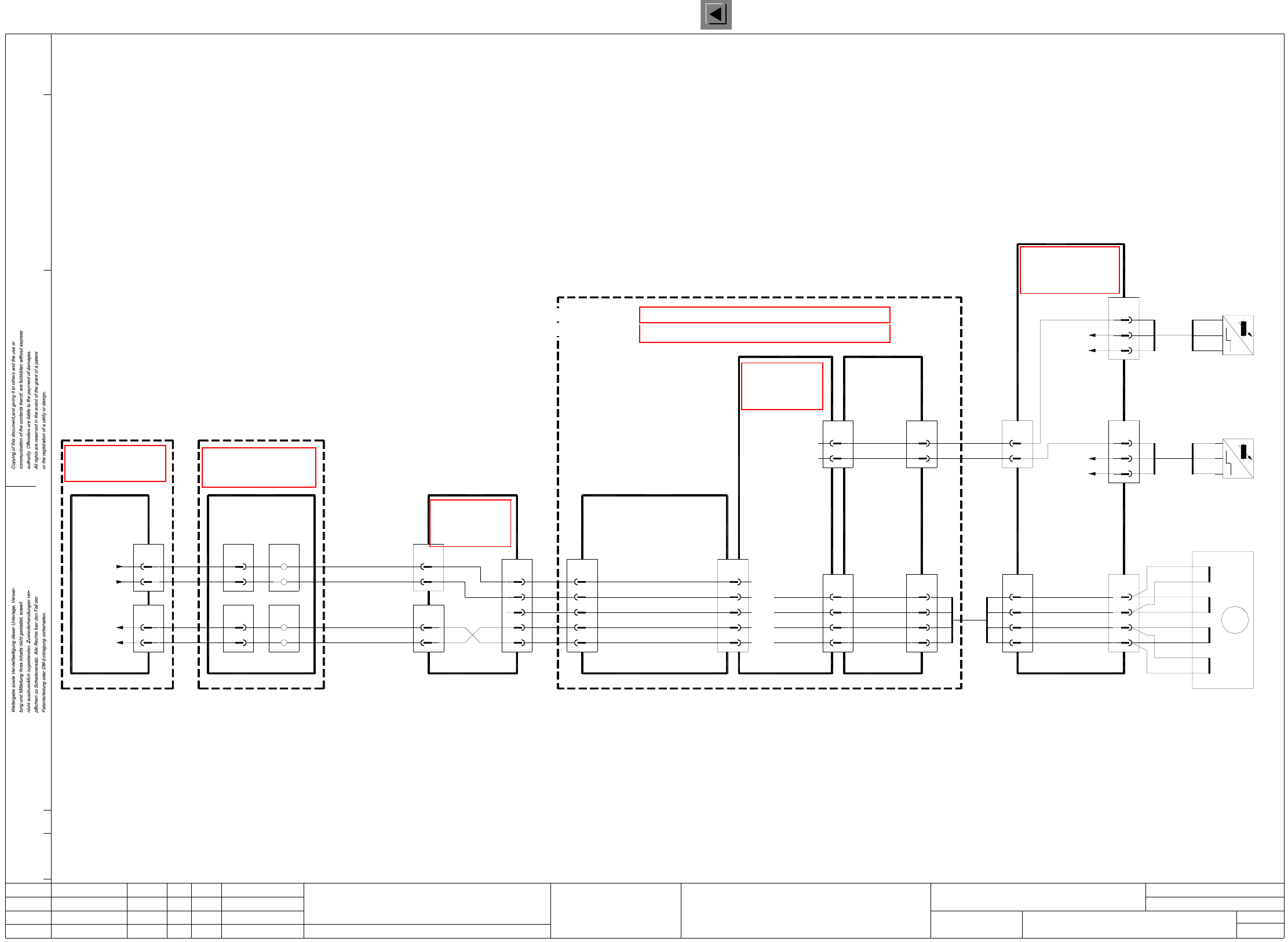
LP03 PCB conveyor 1, lifting table control
br
GND
10
X8
+24VDC
X28
2
3
6
bk
br
bl
lifting table 1 bottom
Sensor switch,
00326021-xx
bk
br
bl
A1
+
-
’dual conveyor’
Conversion board
00325581-xx
+24VDC
GND
6
3
bl
br
X26
2
bk
lifting table 1 top
Sensor switch,
bl
br
-
+
00326020-xx
bk A1
X14
2
3
1
orwh
rd
or
4
br
brwh
rdwh
yewh
ye
lifting table 1
00326034-01
Motor
+
-
-
+
+
-
-
+
A
A
B
B
M
12
X9
6
5
7
8
wh
ye
gn
Stroke 1 B+
Stroke 1 A-
LP3.DWG
Stromlaufplan/Circuit diagram
PL EA
Hi
18.12.2000
SIEMENS
Sh.
Sh.
SMD Placement System SIPLACE F5
1
1
PCB conveyor 1
Lifting table control
Conversion board
00325581-xx
’Dual conveyor’
X12
1
2
X13
4
5
X1kb
X1ka
X2kb
X2ka
6
5
5
6
1
A1
2
2
1
wh
br
gr
ye
00344266-xx
left-hand side
Terminal panel
conveyor 1
Lifting table 1 down
Lifting table 1 up
conveyor 1
Lifting table 1 top
Lifting table 1 bottom
End signal
End signal
00320777-xx
(Cable)
(Cable)
00317876-xx
Port E1.1
Port E1.0
X4se
6
X2se
6
5
5
I/O cards
Port A1.1
Port A1.0
00321497-xx
(Cable)
00321499-xx
(Cable)
00326061-xx
(Cable) (Cable)
00326064-xx
Control unit
00341851-xx
Status Modified Date Name Stand.
Check.
Author
Date
Mat. no.:
CAD file:
Orig./Creat. f./Creat.by
Stroke 1 B-
Stroke 1 A+
10a,10c
8a,8c
6a,6c
4a,4c
X2a
X1a
18a
17a
4
3
2
1
X4a
12
X3a
10
00325580-xx
Dual stepping
Backplane
wh
br
gn
ye
motor board
Stroke 1 B+
Stroke 1 B-
Stroke 1 A+
Stroke 1 A-
Sensor switch
Lifting table bottom
Sensor switch
Lifting table top
14c
22a
X1a
13c
14a
Dual stepping
00325579-xx
motor board
22c
X3a
20
19
4
5
3
Dual stepping
00325580-xx
Backplane
motor board
Control unit - single conveyor 00331465-xx
Control unit - dual conveyor 00327615-xx
Lifting table 1 down
Lifting table 1 fast/slow
End signal, lifting table 1 bottom
End signal, lifting table 1 top
Lifting table 1 up
00326064-xx
(Cable)
X8
20
19
4
5
3
See page 65
See page 86
See page 121
See page 92
See page 121
See page 121
See page 91
1 Detailed Circuit Diagrams 33
I
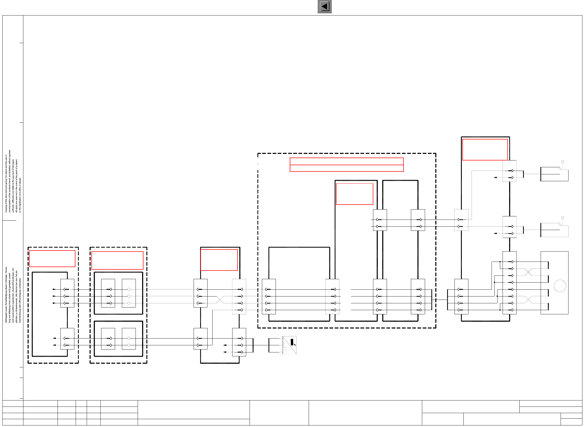
LP04 PCB conveyor 1, width adjustment
LP4.DWG
Stromlaufplan/Circuit diagram
PL EA
Hi
18.12.2000
SIEMENS
Sh.
Sh.
SMD Placement System SIPLACE F5
1
1
PCB conveyor 1
Width adjustment
20a/c
18a/c
15a/c
14a/c
X2a
X1a
18c
17c
8
7
6
5
X4a
13
X3a
11
00325580-xx
Dual stepping
Backplane
gr
pk
bl
rd
motor board
Width 1 B-
Width 1 B+
Width 1 A-
Width 1 A+
width adjustment 1
narrower
End position:
width adjustment 1
16a
16c
X1a
15a
Dual stepping
00325579-xx
motor board
21a
X3a
17
9
6
8
Dual stepping
00325580-xx
Backplane
motor board
Control unit - single conveyor 00331465-xx
Control unit - dual conveyor 00327615-xx
Width adjstm. 1 fast
Width adjstm. 1 wider
Width adjstm. 1 narrower
End pos., width adjstm. 1
00326064-xx
(Cable)
X24
3
2
Conversion board
00325581-xx
’Dual conveyor’
X12
4
5
rd
11
X8
+24VDC
X32
2
3
narrower
00326019-xx
br
gn
wh
’dual conveyor’
Conversion board
00325581-xx
3
2
wh
gn
X30
wider
wh
gn
00326018-xx
br
X16
6
7
5
orwh
rd
or
8
br
brwh
rdwh
yewh
ye
width
00326033-xx
Motor
+
-
-
+
+
-
-
+
A
A
B
B
M
13
X9
2
1
3
4
bl
pk
gr
Width 1 B+
Width 1 A-
Width 1 B-
Width 1 A+
X13
2
3
X1kb
X1kg
X2kb
X5kg
9
8
10
11
6
A1
7
5
4
ye
gr
gn
br
00344266-xx
left-hand side
Terminal panel
width adjstm., conveyor 1
conveyor 1
Sensor switch: position
End signal: width adjstm.
00320777-xx
(Cable)
(Cable)
00317876-xx
Port E1.4
Port E1.3
X4se
9
X3sf
11
10
8
I/O cards
Port A4.6
Port A4.5
00321502-xx
(Cable)
00321499-xx
(Cable)
00326061-xx
(Cable) (Cable)
00326064-xx
Control unit
00341851-xx
A4
5
wh
9
9
Port A4.4
1
6
9
8
X8
6
17
+24VDC
GND
fast, conveyor 1
Motor, width adjustment
Motor, width adjustment
narrower, conveyor 1
Motor, width adjustment
wider, conveyor 1
Position width adjustment 1
00326017-xx
bk
br
bl
A1bk
bl -
br +
Sensor switch,
wider
End position:
+24VDC
gn
wh
3
4
2
1
adjustment 1
width adjustment 1
Limit switch
width adjustment 1
Limit switch
2
1
4
4
2
1
Status Modified Date Name Stand.
Check.
Author
Date
Mat. no.:
CAD file:
Orig./Creat. f./Creat.by
See page 65
See page 86
See page 121
See page 121
See page 92
See page 121
See page 91