Detailed Circuit Diagram Folder SIPLACE F5.pdf - 第53页
2 Circuit Diagr ams 53 I 001 17251-0101 01FD3 SIPLACE F5 basic m odule, input/o utput a ssignmen t (Sh. 2 of 2) = SIEMENS AG + PL EA1 E2 C B A 23 F F E D 67 45 1 67 B C D E 8 12 345 Tek Tek Tek 01. 01. 01. 17.0 7.98 17.0…
2 Circuit Diagrams 52
I
00117251-010101FD3 SIPLACE F5 basic module, input/output assignment (Sh. 1 of 2)
=
SIEMENS AG
+
PL EA1 E2
C
B
A
23
FF
E
D
67
451 67
B
C
D
E
8
12
X2sf: 1-4
X2sf: 7
X2sf: 8
X2sf: 5
X2sf: 6
Address
Port A3.2
Port A3.3
Port A3.1
Port A3.0
Port A3.7
Port A3.6
Port A3.5
Port A4.1
Port A4.0
Output
Port A4.7
Port A4.6
Port A4.5
Port A4.4
Port A4.3
Port A4.2
Output
Port A3.4
Signal designation
+30VDC switched
Motor, spare, on slow
Motor, spare, on fast
Conversion
board,
X2sf: 6
X2sf: 5
X2sf: 8
X2sf: 7
X2sf: 1-4
Plug design. I/O terminal
GND
+30VDC switched
GND
+24VDC
Motor, width adjustment wider, conveyor 1
Motor, width adjustment fast, conveyor 1
Component counter
A4/X3kg:15
A4/X3kg:14
A4/X5kg:G
X2sf:11
X2sf:10
X2sf:12
X3sf: 6
X3sf: 5
X3sf: 1-4
X2sf:13-14
A4/X4kg:18
A4/X5kg:5
A4/X5kg:6
A4/X5kg:7
A3/X2kf:P
A4/X5kg:8
A4/X5kg:M
X3sf: 8
X3sf: 9
X3sf:11
X3sf:10
X3sf:12
X4sf: 1-4(*)
X3sf:13-14
X3sf: 7 A4/X4kg:19
X2sf: 9
PCB handling
Motor, center conveyor on slow, conveyor 1
Motor, center conveyor on fast, conveyor 1
Motor, PCB input conveyor on fast, conveyor 1
Motor, output conveyor on fast, conveyor 1
Motor, output conveyor on slow 2, conveyor 1
Motor, output conveyor on slow 1, conveyor 1
’Received’ to previous station from conveyor 1
’Permission’ to previous station from conveyor 1
Motor, width adjustment narrower, conveyor 1
’Transferred’ to following station from conveyor 1
’Request’ to following station from conveyor 1
Input
Port E3.4
Port E3.6
Port E3.7
Port E3.5
Port E3.3
Port E3.2
Port E3.1
Port E3.0
Input
Port E4.4
Port E4.6
Port E4.5
Port E4.3
Port E4.2
Port E4.1
Port E4.0
Port E4.7
Distance sensor
Crash, portal 1
GND
Bero, nozzle changer SP, portal 2 opened
Bero, nozzle changer SP, portal 1 opened
Bero, nozzle changer SP, portal 1 closed
Bero, nozzle changer SP, portal 2 closed
+24VDC
A3/X2kf:1
A3/X2kf:2
A3/X2kf:3
A3/X2kf:4
A3/X2kf:6
A3/X2kf:7
A3/X2kf:8
A3/X2kf:M
A3/X2kf:5
X4sf: 6
X4sf: 5
X4sf: 8
X4sf: 7
X4sf:10
X4sf:12
X4sf:11
X4sf: 9
X4sf:13-14
A4/X3kg:19
A4/X3kg:18
A4/X5kg:P
A4/X4kg:14
A4/X6kg:5
A4/X6kg:6
A4/X6kg:7
A4/X4kg:15
X5sf: 6
X5sf: 5
X5sf: 8
X5sf: 7
X5sf:10
X5sf:11
X5sf: 9
X5sf: 1-4(*)
GND
A4/X6kg:8
A4/X5kg:M
X5sf:12
X5sf:13-14
Pins marked with an ’*’ are not hard-wired !
Ultrasonic sensor, input conveyor, conveyor 2
Ultrasonic sensor, input conveyor, conveyor 1
Ultrasonic sensor, output conveyor, transport 1
Ultrasonic sensor, output conveyor, transport 2
’Request’ to conveyor 1 from previous station
’Transferred’ to conveyor 1 from previous station
’Permission’ to conveyor 1 from following station
’Received’ to conveyor 1 from following station
Ultrasonic sensor, center conveyor, conveyor 2
Ultrasonic sensor, center conveyor, conveyor 1
Address
Port A1.2
Port A1.3
Port A1.0
Port A1.1
Signal designation
+24VDC
Retract lifting table, PCB release, conveyor 1
Extend lifting table, PCB clamping, conveyor 1
Valve, nozzle changer 2 opened
Valve, nozzle changer 1 opened
Port A1.7
Port A1.5
Port A1.6
Port A2.1
Port A2.0
Output
Port A2.7
Port A2.6
Port A2.5
Port A2.4
Port A2.3
Port A2.2
GND
+24VDC
Valve, ceramic substrate centering, conveyor 1
Valve, extend stopper 2, conveyor 2
Lamp, main fault indicator ready (green)
Valve, extend stopper 1, conveyor 1
Icos MC1
MC1 (M44)
GND
+24VDC
Software release, control on
Lamp, main fault indicator lefthand side (white)
Command ’read PCB barcode’ 2 (contactor relay)
Command ’read PCB barcode’ 1 (contactor relay)
Lamp, main fault indicator righthand side (white)
Output
Compressed air on/off Port A1.4
I/O terminal
A1/X2ka:P
A1/X2ka:1
A1/X2ka:2
A1/X2ka:3
A1/X2ka:4
X2se: 1-4
X2se: 6
X2se: 5
X2se: 8
X2se: 7
Plug design.
A1/X2ka:6
A1/X2ka:7
A1/X2ka:8
A1/X2ka:M
A2/X2kc:2
A2/X2kc:1
A2/X2kc:P
X2se:11
X2se:10
X2se:12
X3se: 1-4
X3se: 6
X3se: 5
X2se:13-14
A2/X2kc:7
A2/X2kc:6
A2/X2kc:5
A2/X2kc:4
A2/X2kc:8
A2/X2kc:M
A1/X2kb:P
X3se: 8
X3se: 9
X3se:11
X3se:10
X3se:12
X4se: 1-4(*)
X3se:13-14
A2/X2kc:3X3se: 7
A1/X2ka:5X2se: 9
Input
Port E1.4
Port E1.6
Port E1.7
Port E1.5
Port E1.2
Port E1.3
Port E1.0
Port E1.1
Input
Port E2.4
Port E2.6
Port E2.5
Port E2.3
Port E2.2
Port E2.1
Port E2.0
GND
Limit switch, width adjustment, conveyor 1
Bero, stopper 1 retracted, conveyor 1
Bero, stopper 2 retracted, conveyor 2
Bero, position width adjustment, conveyor 1
Bero, lifting table bottom position, conveyor 1
Bero, lifting table top position, conveyor 1
Bero, ceramic substrate centering, conveyor 1
Contactor monitoring (software release)
+24VDC
Key-operated switch, 0 -> actuated
EMERG.-STOP button, 1 -> actuated
’Off’ button, 0 -> actuated
Control on, 1 -> K3/K4 on
Protective cover, 1 -> opened
’On’ button, 1 -> actuated
Compressed air sensor, 1 -> compressed air available
Port E2.7
GND
Control on, 1 -> K1/K2 on
A1/X2kb:1
A1/X2kb:2
A1/X2kb:3
A1/X2kb:4
A1/X2kb:6
A1/X2kb:7
A1/X2kb:8
A1/X2kb:M
A1/X2kb:5
X4se: 6
X4se: 5
X4se: 8
X4se: 7
X4se:10
X4se:12
X4se:11
X4se: 9
X4se:13-14
A2/X2kd:2
A2/X2kd:1
A2/X2kd:P
A2/X2kd:7
345
Tek
Tek
Tek
01.
01.
01.
17.07.98
17.07.98
17.07.98
17.07.1998
Tekin
00117251-010101FD3
8
A
1
2
SMD-Placement System SIPLACE 80 F5
Product status
Doc. status
Function status
I/O assignment
SIPLACE 80 F5, basic module
X5se:13-14
X5se:12
A2/X2kd:M
A2/X2kd:8
X5se: 1-4(*)
X5se: 9
X5se:11
X5se:10
X5se: 7
X5se: 8
X5se: 5
X5se: 6
A2/X2kd:3
A2/X2kd:4
A2/X2kd:5
A2/X2kd:6
A2/X2kd:7
A2/X2kd:P
A2/X2kd:1
A2/X2kd:2
X4se:13-14
X4se: 9
X4se:11
X4se:12
X4se:10
X4se: 7
X4se: 8
X4se: 5
X4se: 6
A1/X2kb:5
A1/X2kb:M
A1/X2kb:8
A1/X2kb:7
A1/X2kb:6
A1/X2kb:4
A1/X2kb:3
A1/X2kb:2
A1/X2kb:1
GND
+24VDC
GND
X2se: 9 A1/X2ka:5
X3se: 7 A2/X2kc:3
X3se:13-14
X4se: 1-4(*)
X3se:12
X3se:10
X3se:11
X3se: 9
X3se: 8
A1/X2kb:P
A2/X2kc:M
A2/X2kc:8
A2/X2kc:4
A2/X2kc:5
A2/X2kc:6
A2/X2kc:7
X2se:13-14
X3se: 5
X3se: 6
X3se: 1-4
X2se:12
X2se:10
X2se:11
A2/X2kc:P
A2/X2kc:1
A2/X2kc:2
A1/X2ka:M
A1/X2ka:8
A1/X2ka:7
A1/X2ka:6
X2se: 7
X2se: 8
X2se: 5
X2se: 6
X2se: 1-4
A1/X2ka:4
A1/X2ka:3
A1/X2ka:2
A1/X2ka:1
A1/X2ka:P
+24VDC
GND
MC1 (M44)
Icos MC1
+24VDC
GND
+24VDC
X5sf:13-14
X5sf:12
A4/X5kg:M
A4/X6kg:8
GND
X5sf: 1-4(*)
X5sf: 9
X5sf:11
X5sf:10
X5sf: 7
X5sf: 8
X5sf: 5
X5sf: 6
A4/X4kg:15
A4/X6kg:7
A4/X6kg:6
A4/X6kg:5
A4/X4kg:14
A4/X5kg:P
A4/X3kg:18
A4/X3kg:19
X4sf:13-14
X4sf: 9
X4sf:11
X4sf:12
X4sf:10
X4sf: 7
X4sf: 8
X4sf: 5
X4sf: 6
A3/X2kf:5
A3/X2kf:M
A3/X2kf:8
A3/X2kf:7
A3/X2kf:6
A3/X2kf:4
A3/X2kf:3
A3/X2kf:2
A3/X2kf:1
+24VDC
GND
X2sf: 9
A4/X4kg:19X3sf: 7
X3sf:13-14
X4sf: 1-4(*)
X3sf:12
X3sf:10
X3sf:11
X3sf: 9
X3sf: 8
A4/X5kg:M
A4/X5kg:8
A3/X2kf:P
A4/X5kg:7
A4/X5kg:6
A4/X5kg:5
A4/X4kg:18
X2sf:13-14
X3sf: 1-4
X3sf: 5
X3sf: 6
X2sf:12
X2sf:10
X2sf:11
A4/X5kg:G
A4/X3kg:14
A4/X3kg:15
+24VDC
GND
GND
A2/X2kd:6
A2/X2kd:5
A2/X2kd:4
A2/X2kd:3
X5se: 6
X5se: 5
X5se: 8
X5se: 7
X5se:10
X5se:11
X5se: 9
X5se: 1-4(*)
A2/X2kd:8
A2/X2kd:M
X5se:12
X5se:13-14
Pins marked with an ’*’ are not hard-wired !
Sheet
Sh.
Status DateModified Name Stand. Orig. Creat. f. Creat. by
Author
Date
Check.
2 Circuit Diagrams 53
I
00117251-010101FD3 SIPLACE F5 basic module, input/output assignment (Sh. 2 of 2)
=
SIEMENS AG
+
PL EA1 E2
C
B
A
23
FF
E
D
67
451 67
B
C
D
E
8
12345
Tek
Tek
Tek
01.
01.
01.
17.07.98
17.07.98
17.07.98
17.07.1998
Tekin
00117251-010101FD3
8
A
2
2
SMD-Placement System SIPLACE 80 F5
Product status
Doc. status
Function status
I/O assignment
SIPLACE 80 F5, basic module
Pins marked with an ’*’ are not hard-wired !
X5sg:13-14
X5sg:12
A6/X5ki:M
A6/X6ki:8
X5sg: 1-4(*)
X5sg: 9
X5sg:11
X5sg:10
X5sg: 7
X5sg: 8
X5sg: 5
X5sg: 6
A6/X5ki:15
A6/X6ki:7
A6/X6ki:6
A6/X6ki:5
A6/X5ki:14
A6/X5ki:P
A6/X5ki:18
A6/X5ki:19
X4sg:13-14
X4sg: 9
X4sg:11
X4sg:12
X4sg:10
X4sg: 7
X4sg: 8
X4sg: 5
X4sg: 6
PCB handling
Conversion
board
GND
’Transferred’ to conveyor 2 from previous station
’Permission’ to conveyor 2 from following station
’Request’ to conveyor 2 from previous station
’Received’ to conveyor 2 from following station
+24VDC
Bero, ceramic substrate centering, conveyor 2
Bero, lifting table top position, conveyor 2
Bero, lifting table bottom position, conveyor 2
Limit switch, width adjustment, conveyor 2
Bero, position width adjustment, conveyor 2
GND
Input Input
X2sg: 9
A6/X5ki:19X3sg: 7
X3sg:13-14
X4sg: 1-4(*)
X3sg:12
X3sg: 9
X3sg:10
X3sg:11
X3sg: 8
A6/X5ki:8
A6/X5ki:M
A6/X5ki:18
A6/X5ki:5
A6/X5ki:6
A6/X5ki:7
X2sg:13-14
X3sg: 5
X3sg: 6
X3sg: 1-4
X2sg:12
X2sg:11
X2sg:10
A6/X5ki:15
A6/X5ki:14
A6/X5ki:G
PCB handling
Plug desig.
X2sg: 7
X2sg: 8
X2sg: 5
X2sg: 6
X2sg: 1-4
Conversion
board,
I/O terminal
Motor, output conveyor on slow 1, conveyor 2
Output
Valve, ceramic substrate centering, conveyor 2
Motor, width adjustment narrower, conveyor 2
’Permission’ to previous station from conveyor 2
’Transferred’ to following station from conveyor 2
’Request’ to following station from conveyor 2
Motor, width adjustment wider, conveyor 2
Motor, width adjustment fast, coveyor 2
+24VDC
GND
+30VDC switched
’Received’ to previous station from conveyor 2
Motor, output conveyor on fast, conveyor 2
Motor, output conveyor on slow 2, conveyor 2
Motor, input conveyor on fast, conveyor 2
GND
Output
Extend lifting table, PCB clamping, conveyor 2
Retract lifting table, PCB release, conveyor 2
Motor, center conveyor on slow, conveyor 2
Motor, center conveyor on fast, conveyor 2
Signal designation
+24VDC
Address
Port E6.7
Port E6.1
Port E6.3
Port E6.2
Port E6.6
Port E6.5
Port E6.4
Port E6.0
Port E5.1
Port E5.0
Port E5.2
Port E5.3
Port E5.5
Port E5.7
Port E5.6
Port E5.4
Port A5.4
Port A6.2
Port A6.4
Port A6.3
Port A6.6
Port A6.5
Port A6.7
Port A5.6
Port A5.5
Port A5.7
Port A6.1
Port A6.0
Port A5.1
Port A5.0
Port A5.3
Port A5.2
Sheet
Sh.
Status DateModified Name Stand. Orig. Creat. f. Creat. by
Author
Date
Check.
2 Circuit Diagrams 54
I
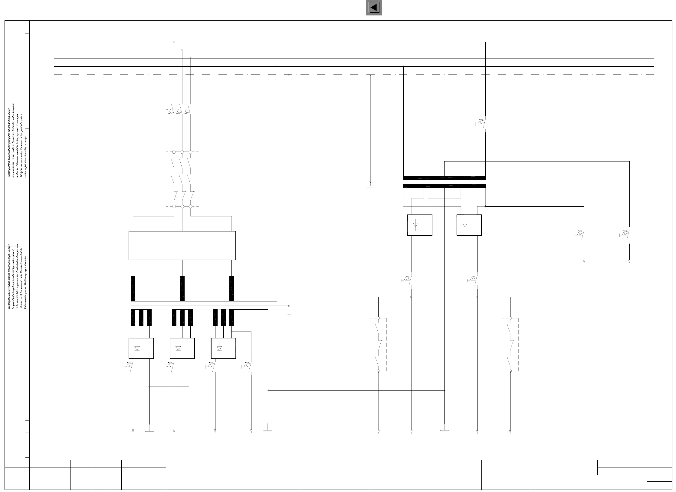
00321086-050101FD3 Circuit diagram overview, safety concept (power unit) (Sh. 1 of 3)
Stromlaufplan/Circuit diagram
(power unit)
Safety concept
Circuit diagram overview
01.
01.
05.
c0952f41_d
23.01.98
Leh
AUT 5
00321086-04
1L+
1L-
3L+2L+
23.01.98
Leh
23.01.98
Leh
Tuth
21.07.98
12345
(x, y axes)
(star/lifting table)
(tape cutter)
4L+
2L-
67
(ext. WPC)
8
SIEMENS
910
switched
24VAC
(x, y slow)
V3
F4 F5 F6
V1 V2
F7
T2
00321086-050101FD3
7L+6L+
2L-
5L+
11 12 13
switched
14 15
(star slow)
(dp1/Z axes)
(Lifting table)
1816 17
K2
F9F8
control unit
To
150VAC
safety circuit
24VAC
To
F2
current limiter
Inrush
A1
K1
L1
L2
L3
PE
N
T1
V5
F10 F11
F3
PE
L3
N
L2
L1
V4
13
14
K2
23
24
Function status
Product status
Doc. status
SMD Placement System Siplace 80S20/F4
1
3Status Modified Orig./Creat. f./Creat.by
Date
Author
Check.
Stand.NameDate
Mat. no.:
CAD file:
Sh.
Sh.