Detailed Circuit Diagram Folder SIPLACE F5.pdf - 第57页
2 Circuit Diagr ams 57 I 0032108 6-050 101LD3 Circuit dia gram, po wer supp ly (Sh . 1 of 2 ) 6 A A1 C D 7 E F 8 5 1 456 78 A E D C B 2 B 34 1 1 23 F 2 gnye bl bk bk bk bk bk 2.5mm ² 2.5mm ² 2.5mm ² bk 1.0mm ² bk 2.5mm ²…
2 Circuit Diagrams 56
I
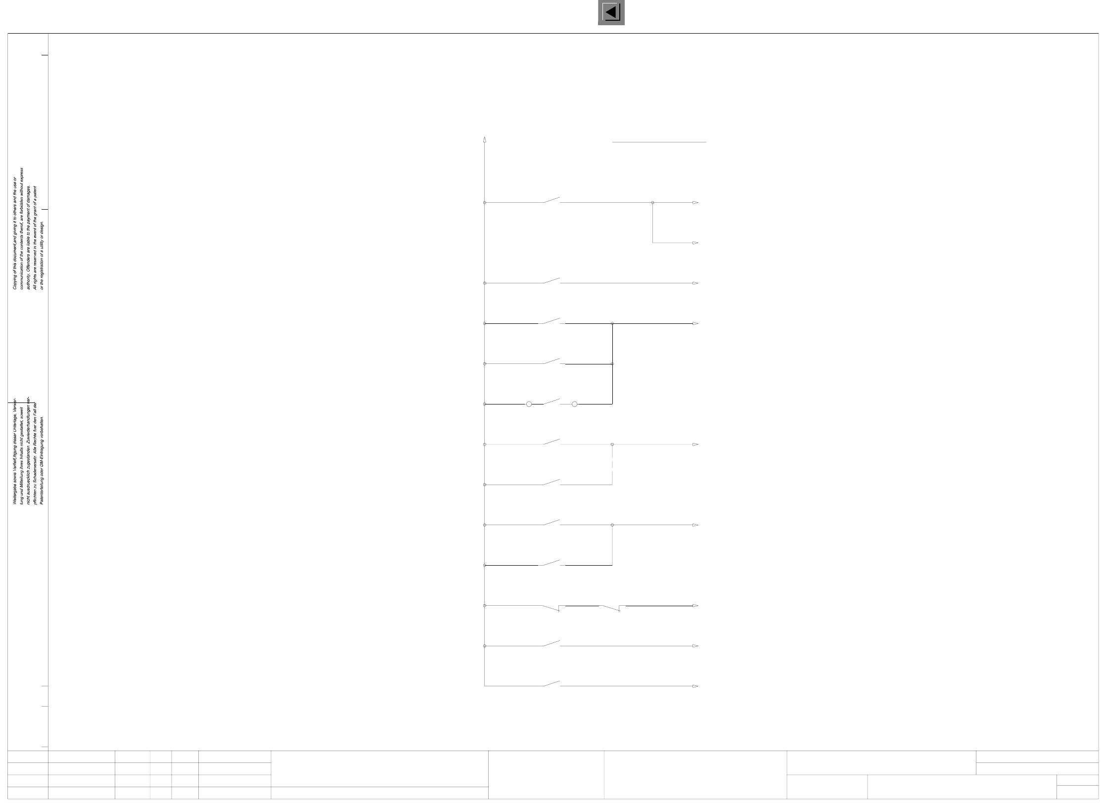
00321086-050101FD3 Safety concept overview (signaling circuit) (Sh. 3 of 3)
c0952f41_d
01.
23.01.98
Leh
21.07.98
Tuth
01.
05.
23.01.98
23.01.98
Leh
Leh
12 435
00321086-04
67
Software release
Key-operated switch
Input/output
Output
Input
Cover switches
(1-n)
Cover switches
AUT 5
Stromlaufplan/Circuit diagram
00321086-050101FD3
Monitoring
software release
SIEMENS
8910
Safety concept overview
(signaling circuit)
11 12
C0952-K3
1513 14 16 17 18
OFF button
Monitoring
Monitoring
key-operated switch
Y0907-S4
Y0907-S3Y0906-S3
Y0907-S2
ON button
Monitoring
Monitoring
cover switches
Y0906-S2
Y0438-S1
Y0413-S1
+24VDC
external
Output
Input
Control ON
Control ON
Monitoring
EMERG.-STOP button
X210
Y0907-S1
Y0906-S1
(SIPLACE 80F)
Monitoring
Monitoring
C0952-K2
C0952-K1
K2
Laser
K1
Signaling circuit
l
Function status
Product status
Doc. status
SMD Placement System Siplace 80S20/F4
3
3Status Modified Date Name Stand.
Check.
Author
Date
Mat. no.:
CAD file:
Orig./Creat. f./Creat.by
Sh.
Sh.
2 Circuit Diagrams 57
I
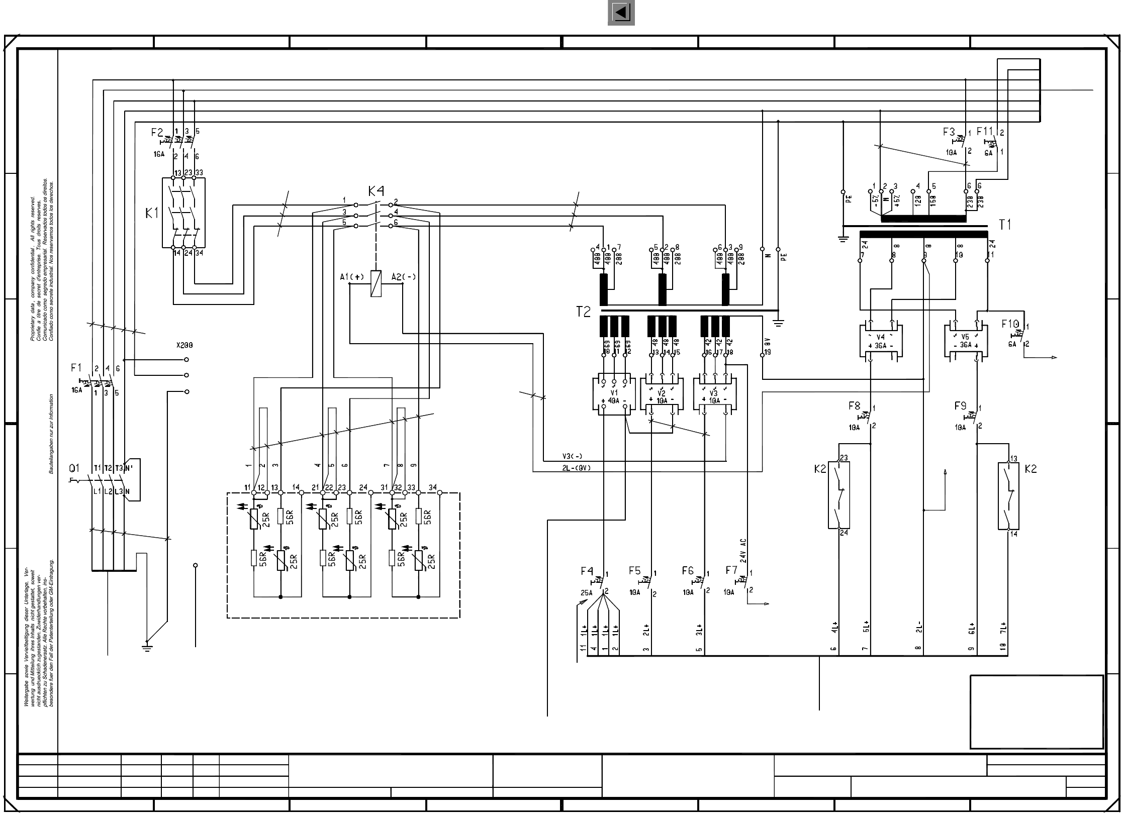
00321086-050101LD3 Circuit diagram, power supply (Sh. 1 of 2)
6
A
A1
C
D
7
E
F
85
1 45678
A
E
D
C
B
2
B
34
1
1
23
F
2
gnye
bl
bk
bk
bk
bk
bk
2.5mm²
2.5mm²
2.5mm²
bk
1.0mm²
bk
2.5mm² bk
GND
To sheet 2
bk bk
1.0mm²
1.5mm²
To
Terminal panel
*903
00300161-06
rd
gr
br
bk
wh
gnye
bl
Status Modified Date Name Stand.
Author
Check.
Date
Orig. Creat. f. Creat. by
PL EA1 E
Function status
Product status
Document status
SMD Placement System SIPLACE 80S20/F4
Sheet
Sh.
To
Terminal panel
*903
C506-W1
To
*903
Terminal panel
1L- C511-W1
in each sleeve
2 wires
To sheet 2
Emerg.-stop, ext.
C0508-W1 gr
Warning!
24V AC
To sheet 2
bk
If the machine is operated with 230 V
connect the inrush current limiter
(i.e. disconnect wire 3 from 13 and connect it to 14,
in parallel
for the other phases
apply this system as appropriate)
disconnect wire 2 from 12 and connect it to 13,
Inrush current limiter
To
00342917-xx (W1)
Cover
Power supplyPower supply
Base
main power filter 1
To
00342193-xx
2.5mm² gnye
PE
gnye
gnye
2.5mm²
bl
bk
bk
br
2.5mm²
Main
switch
00342917-xx (W3)
Remove jumper, if required (IT net)
(France / Italy / Japan / USA)
Jumper is part of the main switch
PE
PE
N
2.5mm²
bk
bk
bk
1.5mm²
bk
1.5mm²
bk
bk
bk
bk
2.5mm²
bk
br
wh
gnye
bl
(Star/lifting table)
(Tape cutter)
bk
bk
bk
(X/Y-axes)
bk
bk
bk
(X, Y slow)
bk
bk
bk
bk
bk
(Star, slow)
(Lifting table)
(DP1/Z-axes)
bk
bk
bk
bk 4.0mm²
10.0mm²
2.5mm²
bk
bk
bk
bk
bk
bk
bk
bk
bk
bl
gnye
bk
2.5mm²
00321086-050101LD3
Circuit diagram, power supply
#
Tuth
21.07.98
23.01.98
23.01.98
23.01.98
01
01
05
Leh
Leh
Leh
=
SIEMENS AG +
FOR INFORMATION ONLY
This document will
not be replaced when
modifications are made !
2 Circuit Diagrams 58
I
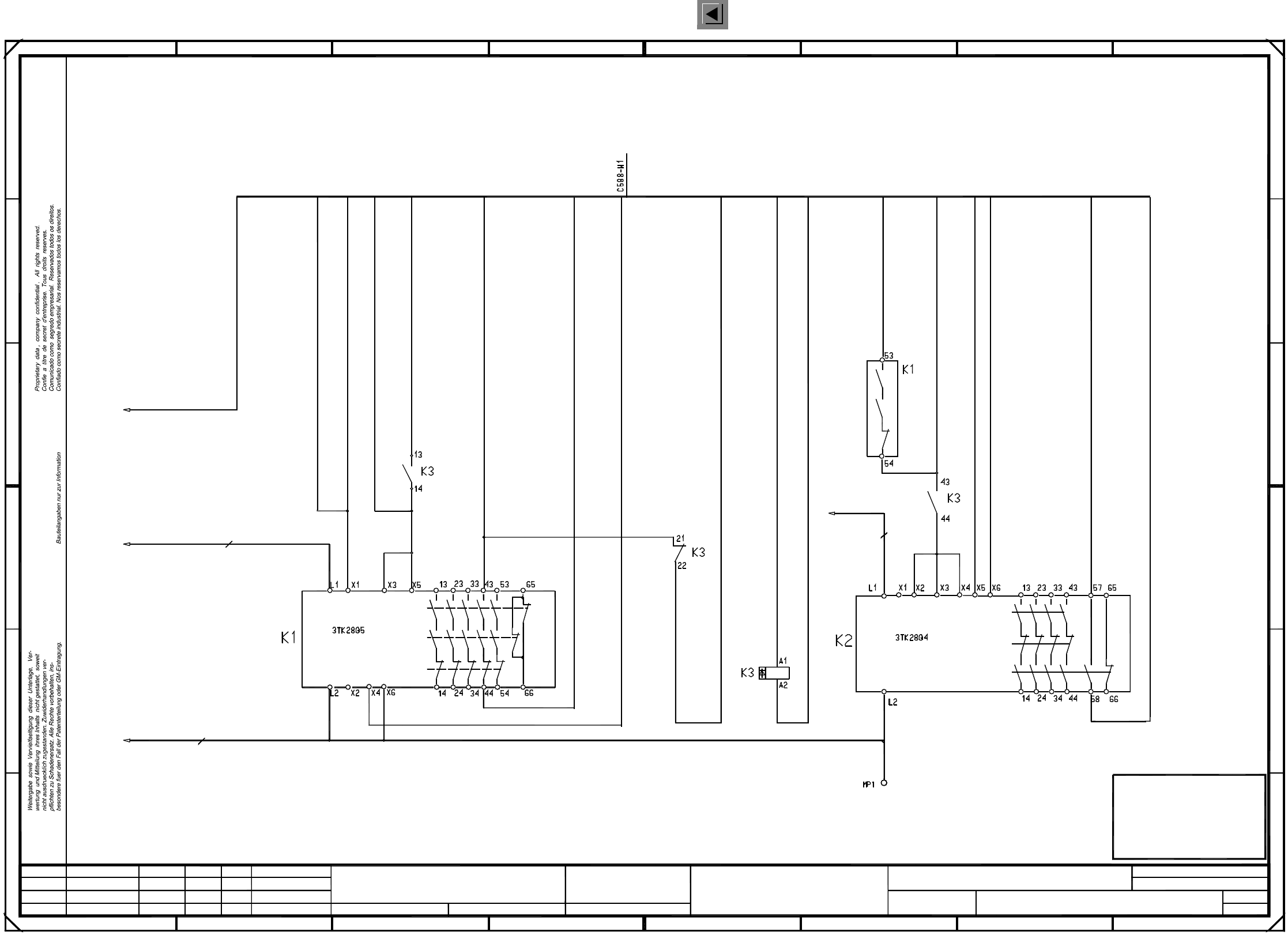
00321086-050101LD3 Circuit diagram, power supply (Sh. 2 of 2)
(to K2)
+24V DC
To S5 input X2kd:1 ye&bn
wh&ye
Status Modified Stand.Date Name Orig. Creat. f. Creat. by
Author
Check.
Date
=
SIEMENS AG
+
FOR INFORMATION ONLY
This document will
not be replaced when
modifications are made !
F F
B
C
D
E
4
D
A
8
1
67
2
2
53 678
12345
E
01
01
05
Leh
Leh
Leh
2
B
A
C
PL EA1 E
00321086-050101LD3
Circuit diagram, power supply
#
Tuth
21.07.98
15.07.98
15.07.98
15.07.98
Function status
Product status
Document status
SMD Placement System SIPLACE 80S20/F4
Sheet
Sh.
GND
To sheet 1
1.0mm²
bk
bk
1.0mm²
To sheet 1
24V AC
F10:2
To sheet 1
24V AC
F7:2
switched
To terminal panel
*904
To sheet 1
1.0mm²
F10:2 24V AC
1.0mm²
To ext. EMERG.-STOP circuit (WPC) gr
gnTo On button
24V AC wh
24V AC br
From EMERG.-STOP circuit (to K1) bl
+24V DC wh&gn
From On button ye
To S5 input X2kd:8 bn/gnControl On
Signaling circuit
Software release
Signaling circuit
To S5 input X2kb:7 wh&gr
Software release To S5 output X2kc:8 gr/bn
Software release To GND, S5 assembly X2kc:M pk&bn
To On button gr&pk
To keyswitch vi
From On button rd&bl
From EMERG.-STOP circuit bk