Detailed Circuit Diagram Folder SIPLACE F5.pdf - 第61页
2 Circuit Diagr ams 61 I 0032108 6-050 101 TD3 Power supply stru cture ( Sh. 3 of 4) 3 4 Leh Leh 05 01 01 13.02.98 13.02.98 13.02.98 21.07.98 Tuth # Power supply stru cture 00321086-050101 TD3 PL EA1 E Leh Function statu…
2 Circuit Diagrams 60
I
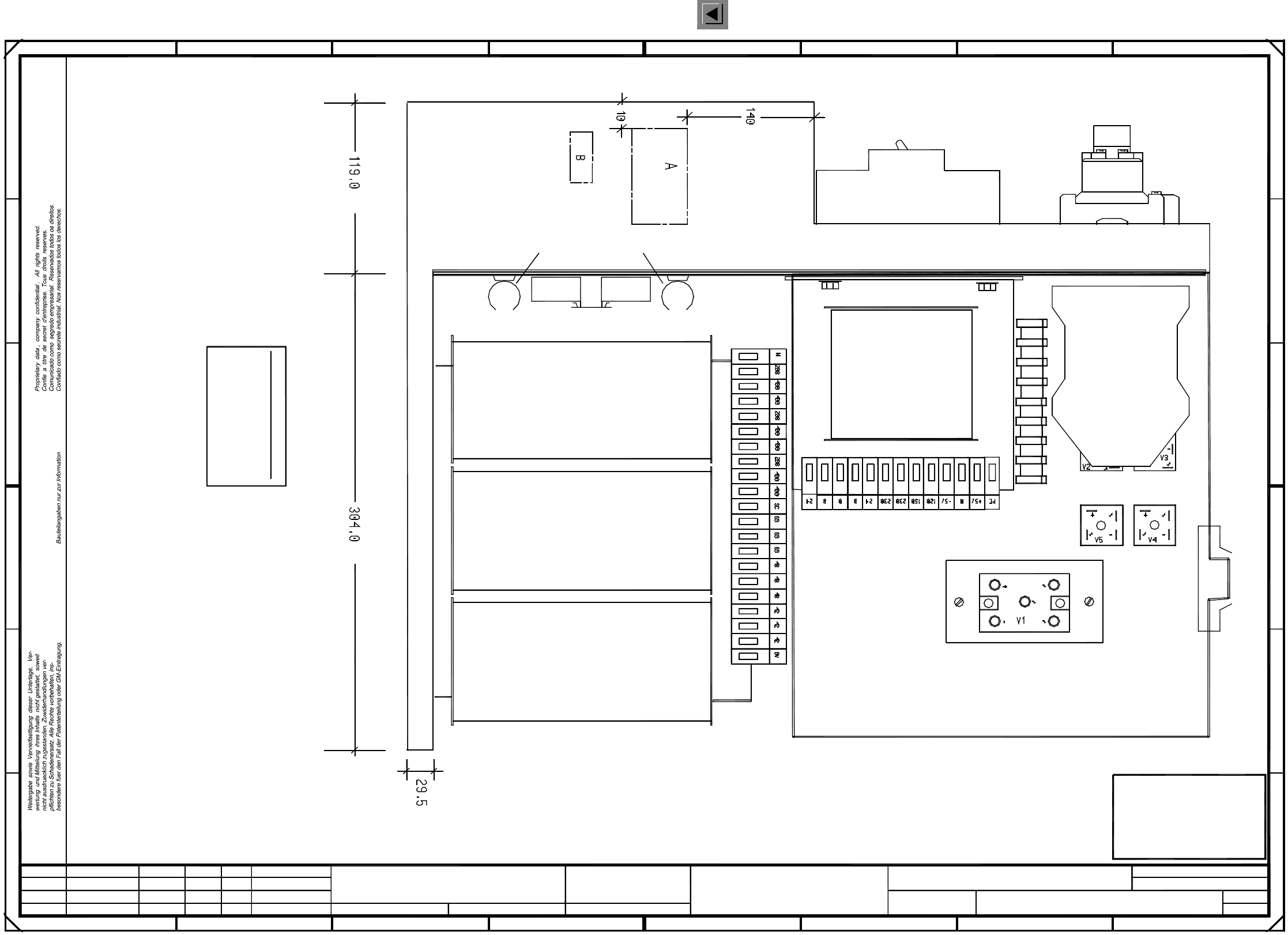
00321086-050101TD3 Power supply structure (Sh. 2 of 4)
Function status
Product status
Document status
SMD Placement System SIPLACE 80S20/F4
Sheet
Sh.
Connections may not
protrude from the terminals!
the cable harness to the machine
Point to fit
Single-phase transformer
T1
Three-phase transformer
T2
Fit both cable ducts
using additional
rivets
Cables must not protrude from
the upper edge of the frame!
Fit K4 protection flush with the right!
Combine the cable using cable ties.
Stand.Status DateModified Name Orig. Creat. f. Creat. by
Author
Check.
Date
=
SIEMENS AG
+
FOR INFORMATION ONLY
This document will
not be replaced when
modifications are made !
2
4
3 54
K4
A1
Leh
Leh
Leh
05
01
01
23.01.98
23.01.98
23.01.98
21.07.98
Tuth
#
Power supply structure
00321086-050101TD3
PL EA1 E
8
A
FF
E
D
12 8
1234567
C
B
A
B
C
D
E
67
2 Circuit Diagrams 61
I
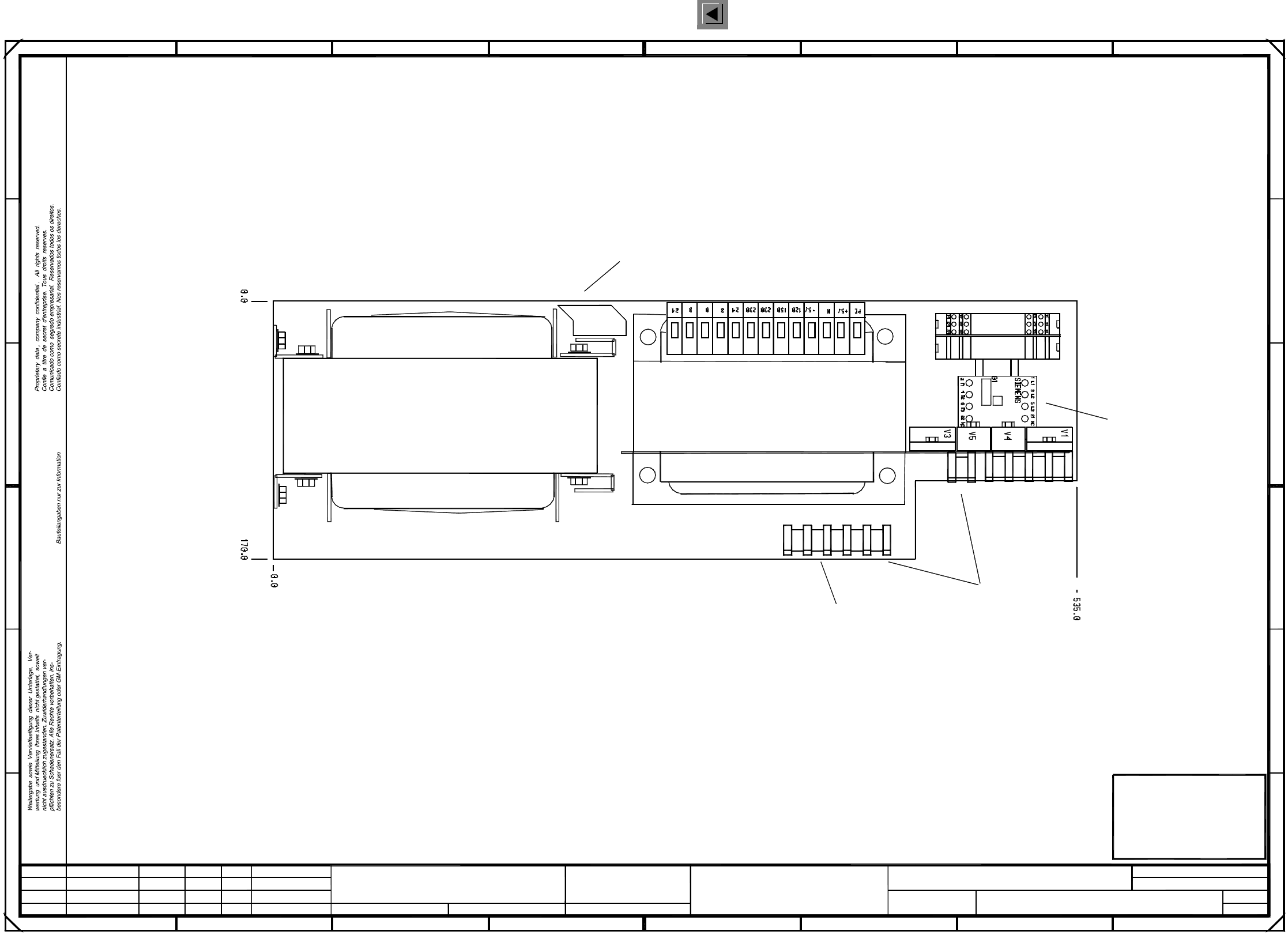
00321086-050101TD3 Power supply structure (Sh. 3 of 4)
3
4
Leh
Leh
05
01
01
13.02.98
13.02.98
13.02.98
21.07.98
Tuth
#
Power supply structure
00321086-050101TD3
PL EA1 E
Leh
Function status
Product status
Document status
SMD Placement System SIPLACE 80S20/F4
Sheet
Sh.
Oval-shaped cable duct: dia.=30mm l=100mm
T2
Single-phase transformer
T1
limiter
A1
Inrush current
Cable duct: dia.=20mm l=110mm
Edge protection
Three-phase transformer
The following labels have to be applied:
A: identification label, assembly inscription acc. to VA-F-510-001 AUT5
B: inspection label, inspection inscription of products acc. to guideline VA-F-510-001
SIEMENS PLEA1
PLEA1 Serial No.: ...
ES 1 2 3 4 5 6 7 8 9 10
Serial No.
Stand.Status DateModified Name Orig. Creat. f. Creat. by
Author
Check.
Date
Mat. no.: 00321086-05
Type 4AV1301-3CT
=
SIEMENS AG
+
FOR INFORMATION ONLY
This document will
not be replaced when
modifications are made !
345
12345
C
B
A
2 6781
678
A
D
E
B
C
D
E
FF
2 Circuit Diagrams 62
I
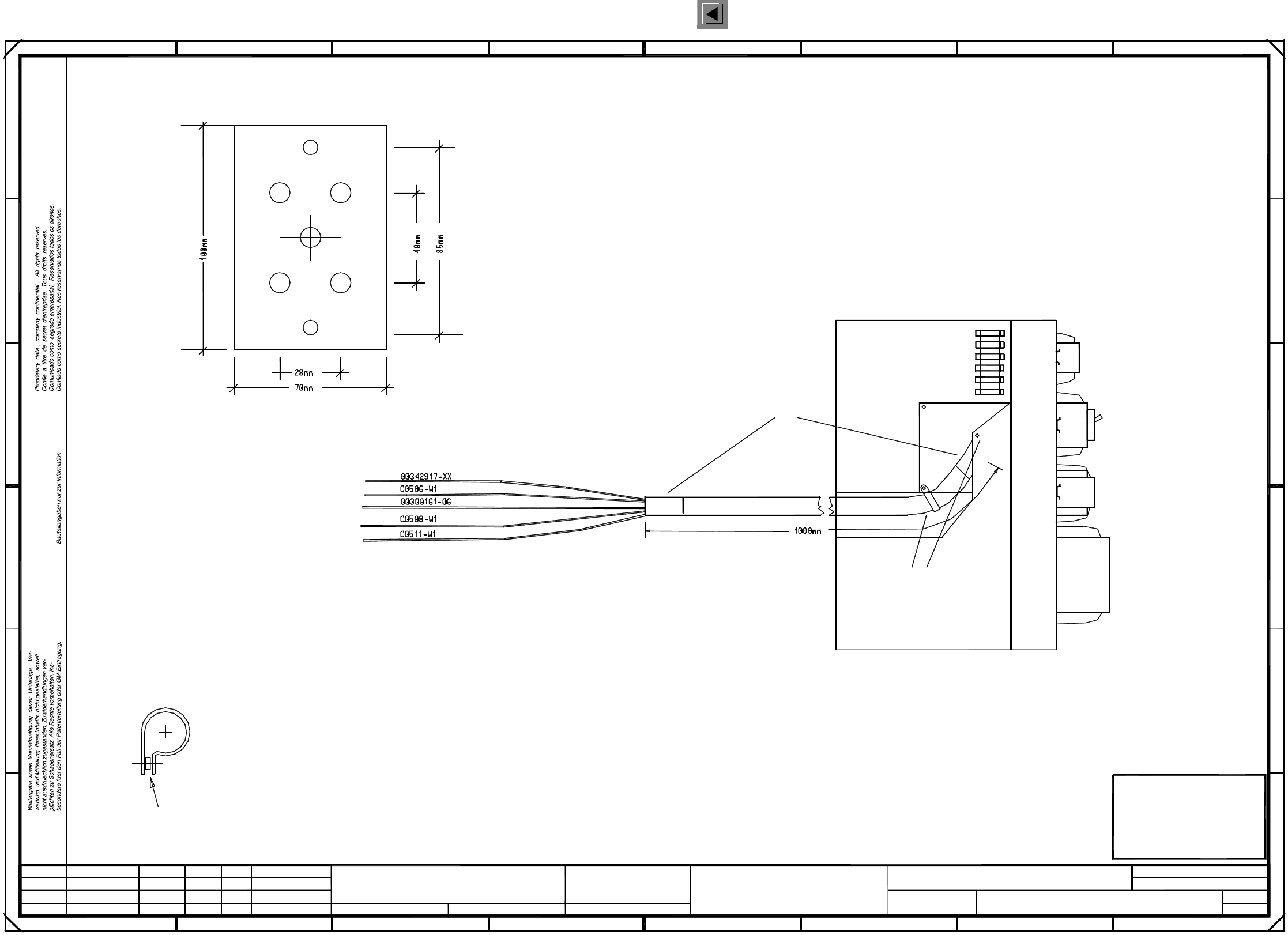
00321086-050101TD3 Power supply structure (Sh. 4 of 4)
=
SIEMENS AG
+
4
4
45678
1 678
A
B
C
D
E
FF
E
D
C
B
A
Leh
Leh
Leh
05
01
01
23.01.98
23.01.98
23.01.98
21.07.98
Tuth
#
00321086-050101TD3
123
2345
PL EA1 E
Function status
Product status
Document status
SMD Placement System SIPLACE 80S20/F4
Sheet
Sh.
Power supply structure
not be replaced when
This document will
FOR INFORMATION ONLY
modifications are made !
No. Modified Date Name Stand.
Check.
Author
Date
Orig. Creat. f. Creat. by
The cover for the V1 bridge rectifier is to be
fitted using a distance bolt of 50 mm length and M4 thread.
To increase the diameter of the fastening clip,
3 distance plates have to be inserted when fitting the clip.
Please note!
Cover for V1 bridge rectifier
Break and chamfer edges
Holes: symmetrical
Material: Makrolon, transparent, 1.5mm
2 x dia. = 4.5mm
5 x dia. = 6mm
2 x 10 cm shrink sleeve
Protective sleeve
2 x fastening clip