Detailed Circuit Diagram Folder SIPLACE F5.pdf - 第76页
2 Circuit Diagr ams 76 I 0033463 8-010 102TD3 S ervo uni t, assembli es overvi ew (Sh. 2 of 2 ) TBS120/2,5S Servo board, Z-axis SP head Servo board, DP1-axis TDS120A2,5Z TDS120/1D +15V -15V GND +15V -15V Power supply uni…
2 Circuit Diagrams 75
I
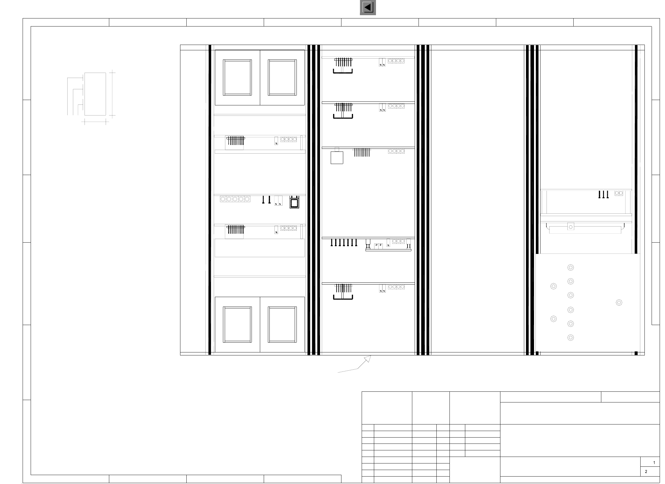
00334638-010102TD3 Servo unit, viewed from the front (Sh. 1 of 2)
Dynamic brake, X, "A8"
DR-axis, IC head "A6"
Z-axis, IC head "A7"
001 002 003 004 005 005
008 009
5V12V24V6L+
GND
007
Star, SP head "A5"
Z-axis, SP head "A4"
Siemens AG
1
1
243
2345678
A
B
C
D
E
F
A
B
C
D
AUT5-BSM
SMD-Placement System Siplace 80F4
Product status
Doc. status
Function status
6-nozzle revolver head
A: Identification label, assembly inscription according to recommendation VA-F-510-001
(flush with the front plate):
Apply the following labels inside
* Note
B: Inspection label, identification: testing eng., year, month
Manufacturer/location of plant according to SN 37040
Date (year/month/day) according to SN 01007
Numeral
"A20"
Sheet
Sh.
Scale
Date
Author
Check.
Stand.
CAD-Datei:
Mat-Nr.:
Status Modified Date Name
334638T2
2. Tek04.11.97
16.09.97 Tek
Tek16.09.97
1.
1.
Tekin
16.09.1997
Servo unit 80F4 / 6
00334638-010102TD3
(viewed from the front)
00334638-01
1:2
* Note
2L+/5L+
2L+
7L+2L+/5L+
SIEMENS AUT 5
AA-BBBB-CCCC
00334638 / 01
40
18
Fan unit
Power supply unit "A12"
Anti-crash board "A10"
Dynamic brake, Y, "A9"
Y-axis "A2"
X-axis "A1"
L3
L4
L1
L2
DP1-axis, SP head "A3"
"A11" ballast circuit
2 Circuit Diagrams 76
I
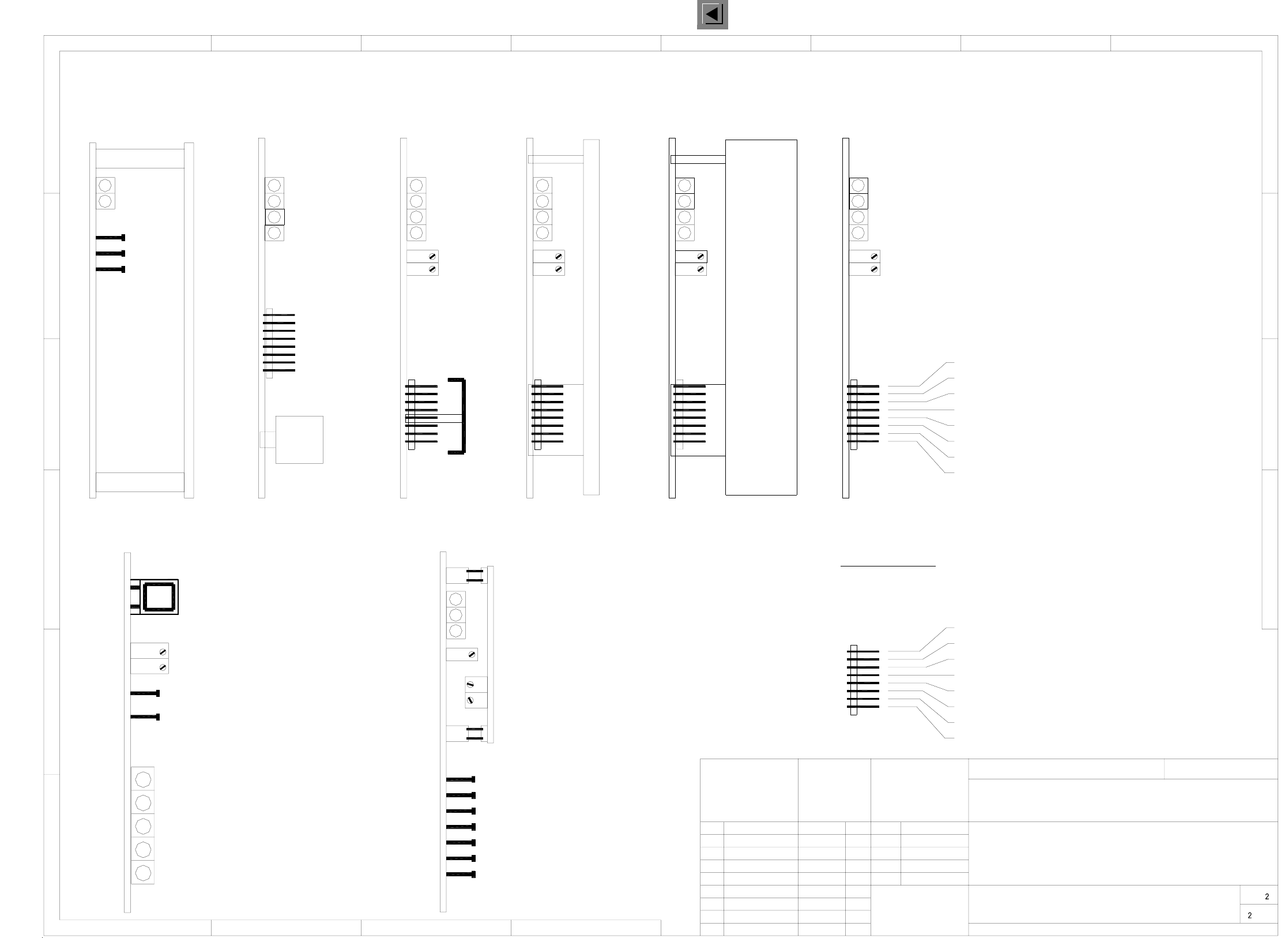
00334638-010102TD3 Servo unit, assemblies overview (Sh. 2 of 2)
TBS120/2,5S
Servo board, Z-axis SP head
Servo board, DP1-axis
TDS120A2,5Z
TDS120/1D
+15V
-15V
GND
+15V
-15V
Power supply unit
Servo board, star-axis
Ready
Output stage release
I r.m.s. limiting (I² x t signal)
Malfunction
P gain
Tachometer
Servo board, TDS120
TDS120/25Y
Servo board, Y-axis
Reset button
Zero point, distance sensor
Amplification, distance sensor
Corresponding voltages, distance sensor
X-axis, gantry I
X-axis, gantry II
Y-axis, gantry I
Y-axis, gantry II
Distance sensor
0V
MP1 Nominal speed
MP2 Nominal current value
MP3 Current regulator output
MP4 External I r.m.s. value
MP5 Tacho voltage
MP6 Actual current value
Tachometer
Amplification
Offset, speed control
Malfunction
Ready
I² x t signal
AGND
2. Tek04.11.97
16.09.97 Tek
Tek16.09.97
1.
1.
00334638-01
334638T2
Tekin
16.09.1997
Servo unit 80F4 / 6
00334638-010102TD3
(Assemblies overview)
TRS120/2S
Servo board, DR-axis IC head
Servo board, TRS120
Anti-crash board
Siemens AG
1
1
243
2345678
A
B
C
D
E
F
A
B
C
D
AUT5-BSM
TBS120/2,5S
Pin assignment of servo board, star-axis
*) Note !
le Nominal power input
Ns Nominal speed
li Actual current value
IA Motor manipulated variable (current reg. output)
ls Nominal current (speed controller output)
Ta Tacho (real tachometer voltage)
Ss Sensor-stop signal
0V GND amplifier electronics
MP2: Current - nominal value 'I-S (W)'
MP1: Current - nominal value 'I-S (U)'
MP6: Current regulator output 'U-nom (W)
MP5: Current regulator output 'U-nom (U)
MP4: Current - actual value 'I-ist (W)'
MP3: Current - actual value 'I-ist (U)'
MP6: Spare
MP7: Reference potential '0V'
*) Note !
Servo board, Z-axis IC head
TDS120A2Z
TDS120/12,5X
Servo board, X-axis
SMD-Placement System Siplace 80F4
Product status
Doc. status
Function status
6-nozzle revolver head
Sheet
Sh.
Scale
Date
Author
Check.
Stand.
NameDateModifiedStatus
CAD-Datei:
Mat-Nr.:
2 Circuit Diagrams 77
I
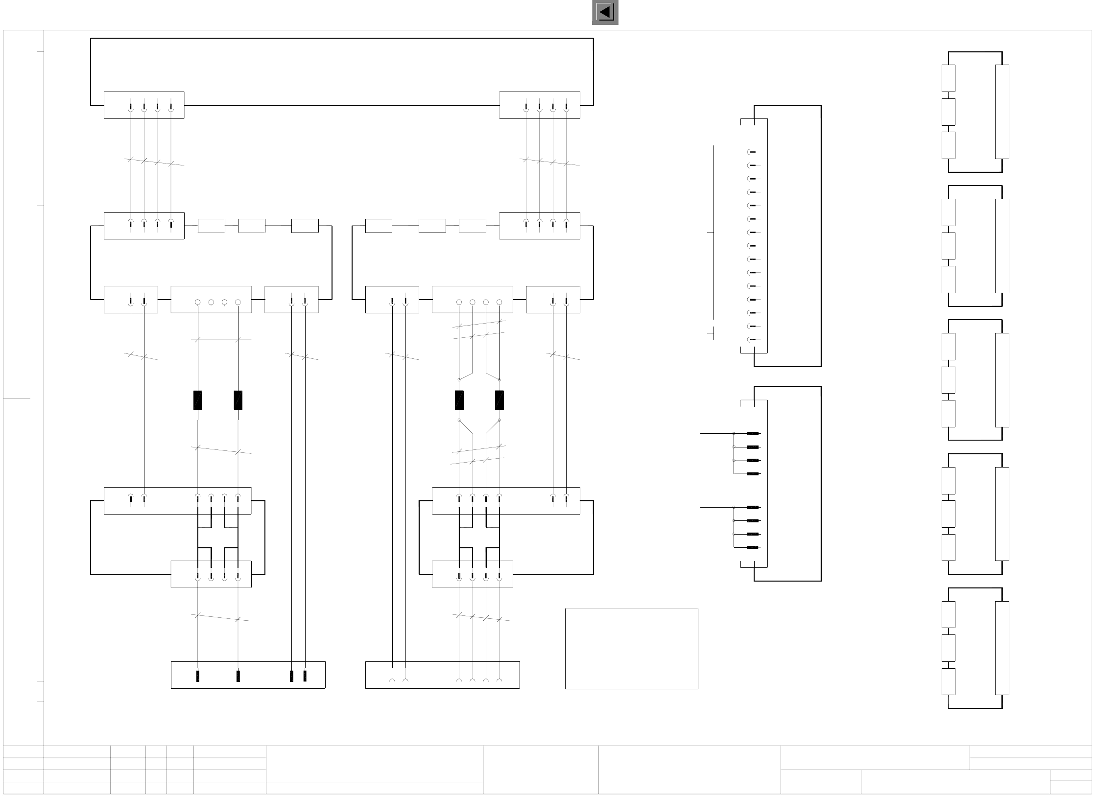
00334647-010101LD3 F5 servo unit, basic module (Sh. 1 of 3)
pkbk
X3va 1
1L+/4L+
2 3
T+
T-
EN
X11a 1
yebk
yebk
yebk
2 3
5613X5 6X6 5 3412
00334647-01
334647L1
16.09.1997
Tekin
Motor -
Motor +
Tacho -
Tacho +
Tacho -
Tacho +
Motor -
Motor -
Motor +
Motor +
Servo unit 80F4 / 6
Base
Voltage
(vk)
X4vk
M+
M-
br
pk
X7
4z
20z
6d
22d
br
vi
T-
T+
8z
M-
16z
10d
18d
M+
br
L1
0,4H
pk
L2
0,4H
T-
T+
M-br 4z
M-
br
pk
T-
T+
br
X8
M+
M+
vi
vi
X-axis
Dynamic
20z
6d
22d
brake
M-8z br
T-
T+
X8
M- br
L3
Brake signal
16z
10d
18d
M+
M+
24z
vi
vi
L4
0,4H
0,4H
A13
2 1 6X7va 5
brbk
pkbk
X6va
X-axis
4
X2va
3X5va 1
br
vi
X1va
4
Y-axis
X6vb
brbk
X5vb 1 3 X7vb 5
br
pk
brbk
Backplane
1L+/4L+
X1vb
X2vb
X4vb 1 4 6 1 2
vibk
vibk
wh
pkbk
X3vb 1
A14
2 3 4
EN 15V
T+
T-
EN
X11b 1
yebk
yebk
yebk
yebk
2 3 4
Motor
N O T E to */**
c8
c6
26d
1L+/4L+
c4
c2
a8
a6
1L-
X13
a2
a4
Setpoint values
Tachometer
Motor
X3vk X2vk
Voltage
(vg)
X4vg
Ballast circuit
Motor
Tachometer
Setpoint values
X2vgX3vg
Voltage
X4vc
(vc)
X3vc
-15V
Input
6L+
1L-
-15V
30
32
28
Output
-15V
-15V
-15V
24
26
22
-15V
1L-
18
20
16
4
10
+15V
+15V
+15V
14
12
+15V
+15V
+15V
8
6
X12
(ñ15V)
Power supply unit
(vd)
Setpoint values
X2vc
Tachometer
Motor
Voltage
X4vd X3vd
Voltage
X4vf
Setpoint values
X2vd
(vf)
Setpoint values
Motor
Tachometer
X3vf X2vf
21
21
21
21
Date Name Stand.
Check.
Author
Date
Mat-Nr.:
Upkpr./Epk.f./Epk.d.
Sheet
Sh.
1.0mm²1.0mm²
1.0mm²**
1.0mm²**
1.0mm²**
0.25mm²
1.0mm²*
0.25mm² 0.25mm²
1.0mm²*
1.0mm²*
0.25mm²
0.25mm²0.25mm²
AUT5-BSM
Siemens AG
Stromlaufplan/Circuit diagram
19181716151413121110987654321
Siemens AG
Stromlaufplan/Circuit diagram
19181716151413121110987654321
Function status
Product status
Doc. status
SMD Placement System Siplace 80F4
1
3
6-nozzle revolver head
Twist wires in pairs and
keep cable routing short.
When installing wires make
sure to separate wires
marked with * or **.
Please also refer to the
servo rear panel drawing
in the construction specifications
Status Modified
00334647-010101LD3
3L+
3L+
2L+/5L+
3L+
3L+
A15
DP1-axis
Backplane
X1vf
A16
X1vd
Backplane
Z-axis
A17
X1vc
Backplane
star
A18
DR-axis
Backplane
X1vg
A19
X1vk
Backplane
Z-axis
Anti-crash board
yebkEN 15V
Backplane
1.
1.
1.
16.09.97
16.09.97
16.09.97
Tek
Tek
Tek
X-axis
Dynamic
brake
Brake signal
X7
24z
26d
4X4va 1
wh