00197961-01_UM_JTF-MW_on_SIPLACE_E_en - 第23页
Technical Data of the SIPLACE JTF-MW 3.1.1 Location of Electrical Parts Dimensions of the JTF-MW User Manual JTF-MW on SIPLACE E 23 SIPLACE JTF-MW – sid e view from the front 3.2 3 . 2 D im e n s io n s o f t h e J T F -…
Technical Data of the SIPLACE JTF-MW
Overview the SIPLACE JTF-MW Feeder 3.1.1 Location of Electrical Parts
22 User Manual JTF-MW on SIPLACE E
3.1.1
3.1.1 Location of Electrical Parts
Location of Electrical Parts
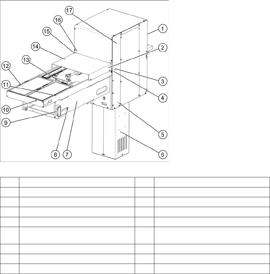
SIPLACE JTF-MW – side view from the rear
1 JTF MW HMI board [03118381-xx] 2 Conveyor motor [03113373-xx]
3 Tray slot sensor (receiver) [03113297-xx] 4 Gap sensor (emitter) [03113297-xx]
5 Sensor bottom position [0311298-xx] 6 LEYG40MC-250B-AP [03113284-xx]
7 JTF-MW control board [03116629-xx] 8 E-adapter board [03116253-xx]
9 Pogo pin board [03113686-xx] 10 Sensor tray stop @ end [03113377-xx]
11 Conveyor forward slow down sensor
(receiver) [03113297-xx]
12 Conveyor forward slow down sensor
(emitter) [03113297-xx]
13 Valve assembly unit [03114171-xx] 14 Return slow down sensor [03113298-xx]
15 Gap sensor (receiver) [03113297-xx] 16 Tray slot sensor (emitter) [03113297-xx]
17 Sensor top position [03113298-xx]
Technical Data of the SIPLACE JTF-MW
3.1.1 Location of Electrical Parts Dimensions of the JTF-MW
User Manual JTF-MW on SIPLACE E 23
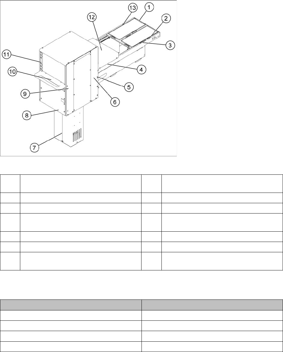
SIPLACE JTF-MW – side view from the front
3.2
3.2 Dimensions of the JTF-MW
Dimensions of the JTF-MW
3.3
3.3 JEDEC Tray Specification
JEDEC Tray Specification
The SIPLACE JTF-MW is designed to process two standard sized JEDEC trays at once (JEDEC Stand-
ard No.95-1, IEC 60286-5).
Other customized JEDEC type trays are also accepted if they match the JTF-MW specification.
The two trays are placed on a steel metal tray carrier (cookie tray) and secured in position by magnets.
1 Sensor tray stop @ end [03113377-xx] 2 Conveyor forward slow sensor (emitter)
[03113297-xx]
3 Conveyor tray clamping [03113382-xx] 4 Return slow down sensor [03113298-xx]
5 Gap sensor (receiver) [03113297-xx] 6 Tray slot sensor (emitter) [03113297-xx]
7 LEYG40MC-250B-AP [03113284-xx] 8 Door switch, reed switch, magnetic,
MK13,0.5M leads 500W [03113299-xx]
9 Tray home sensor [03113298-xx] 10 Feeder kicker air cylinder [03113331-xx]
11 JTF MW HMI board [03118381-xx] 12 Conveyor return pusher [03113370-xx]
13 Conveyor forward slow down sensor (re-
ceiver) [03113297-xx]
Dimensions
Width 322.4 mm
Height 946 mm
Length 1209 mm
Weight ~ 60 kg (including tray carrier and magnets)

Technical Data of the SIPLACE JTF-MW
Pneumatics 3.1.1 Location of Electrical Parts
24 User Manual JTF-MW on SIPLACE E
3.4
3.4 Pneumatics
Pneumatics
Description Unit
JEDEC Tray capacity 15 levels of cookie tray, each handles 2 JEDEC
trays
=> 30 thin JEDEC Standard Trays
Standard JEDEC Tray Type JEDEC Standard No. 95-1, IEC 60286-5
JEDEC Tray width 135.9 + 0.25/-0.13 mm
JEDEC Tray length 322.6 + 0.25/-0.13 mm
Tray thickness See below (total Max 35 mm when skip 2 levels,
Max 11.8 mm
JEDEC Tray Material Trays made of plastic, opaque materials
JEDEC Tray flatness ≥ 0.8 mm over entire surface
JEDEC Tray warpage ≤ 2 mm
Position accuracy Edge of tray 0.05 mm repeatable.
Tray Exchange (fast)
Average try exchange time 9 s
Tray Exchange (Slow)
For sensitive components
About 30 – 50% slower compared to fast.
Total weight of cookie tray 30 kg
Max weight per tray 2 kg +/- 10%.
For heavily loaded trays the balance must be in the
center of the tray.
Maximum force on tray 2 N
Orientation of trays Keyed
Component size vs. Pocket size JEDEC Standard No. 95-1
Mean Time Between Failure (MTBF) 1344 h
Mean Time To Repair (MTTR) 30 minutes
Mean Time Between Maintenance (MTBM) 200 h
Mean Time To Maintain (MTTM) 15 minutes
Mean Time Between Assist (MTBA) 4 h
Mean Time To Assist (MTTA) 2 minutes
Pneumatics Description
Connection 4 mm tube
Pressure 5.0 – 10.0 bar
Compressed air consumption < 28.3 l/min (1SCFM)