00197961-01_UM_JTF-MW_on_SIPLACE_E_en - 第28页
Setting up and Commissioning Overview of Configuration 28 User Manual JTF-MW on SIPLACE E 4.4 4 . 4 O v e r v ie w o f C o n f ig u r a t io n Overview of Configuration Location 2 wi th SIPL ACE JTF-MW installed 1. SIPLA…

Setting up and Commissioning
Scope of Delivery
User Manual JTF-MW on SIPLACE E 27
4
4 Setting up and Commissioning
Setting up and Commissioning
4.1
4.1 Scope of Delivery
Scope of Delivery
The scope of delivery includes the following parts:
Not included are all options like power supplies, mount plates etc. and other accessories for custom ad-
aptation.
4.2
4.2 Unpacking and Checking the Delivery
Unpacking and Checking the Delivery
The JTF-MW is put in a one way crate made of carton.
► After receiving the delivery, check the feeder for transportation damages.
Transportation damages are to be reported with photos and proves directly to the forwarder.
► Other claims are to be reported to ASM within 14 days of receipt of the feeder. For details, refer to
"1.1.1 Warranty" [ ➙ 5]
► Contact ASM to get an RMA number if replacement parts are needed.
► During removal, remember that the SIPLACE JTF-MW (~ 60 kg/~ 132 lb) is heavy. You might need
to enlist the help of a second person.
► Make sure a solid table is available right next to the open crate, to put the feeder on it.
► If you put the feeder in stock, refer to "4.3 Storage" [ ➙ 27].
4.3
4.3 Storage
Storage
In case the feeder is not used after receipt and put in a ware house, please make sure the feeder is in
an upright position. If you are unsure if the feeder is upright, open the crate and check.
The storage location shall be clean and the temperature shall be between -25 °C and +55 °C at a relative
humidity of less than 45% on average.
After storage, the feeder shall be conditioned according to the environmental temperature and humidity
for at least 48 hours (between 15 °C and 25 °C).
Part number Description
03118894-xx SIPLACE JTF-MW feeder, preassembled
03115273-xx JTF-MW table kit
03117595-xx JTF-MW frame kit
03120613-xx Tubing set for JTF-MW
03110329-xx Shortened empty tape duct, ETD 25 mm right
CAUTION
Heavy Weight
The heavy weight of the SIPLACE JTF-MW (~ 60 kg/~132 lb) could cause injuries if the module
is not handled correctly.
► Do not lift or carry the module alone.
► Use lifting aids and proper lifting techniques when removing or replacing.
► You might need to enlist the help of a second person.
Setting up and Commissioning
Overview of Configuration
28 User Manual JTF-MW on SIPLACE E
4.4
4.4 Overview of Configuration
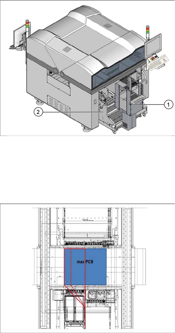
Overview of Configuration
Location 2 with SIPLACE JTF-MW installed
1. SIPLACE JTF MW
2. Changeover table (COT)
4.4.1
4.4.1 Restrictions
Restrictions
If the SILPACE E machine is equipped with a SIPLACE PP head in combination with a SIPLACE CPx
head, the maximum height of components and tray is 16 mm (overall clearance available is 17.5 mm).
Potential collision areas for combined head configuration and high components on the tray carrier
Collisions may occur if the combined height of components and tray is more than 16 mm (overall clear-
ance available is 17.5 mm) if a SIPLACE CPx head picks up a component just beneath the manual tray
handler.
Setting up and Commissioning
Preparatory Work
User Manual JTF-MW on SIPLACE E 29
Component height restrictions for different head combinations
4.5
4.5 Preparatory Work
Preparatory Work
The SIPLACE JTF-MW will be installed on a moveable table system [03105475-xx] (COT) on location
2B in a SIPLACE E machine.
The COT and the host machine must be adapted before the SIPLACE JTF-MW can be installed:
▪ "4.5.1 Retrofitting Work on the COT" [ ➙ 29]
▪ "4.5.2 Retrofitting Work on the Host Machine" [ ➙ 30]
4.5.1
4.5.1 Retrofitting Work on the COT
Retrofitting Work on the COT
Adapt the COT using the following retrofitting kit:
▪ JTF-MW Table Kit [03115273-xx].
Head configuration SIPLACE CP6
& SIPLACE PP
SIPLACE CP12
& SIPLACE PP
SIPLACE TH or
SIPLACE PP
Comments
Max. height of component and
tray
16 mm 16 mm 25 mm Same restric-
tions as for
manual tray.
NOTICE
Collision avoidance
As the machine has no sensors to check the component height in the tray carrier, it is in the
responsibility of the operator to ensure that the height restriction is not violated.
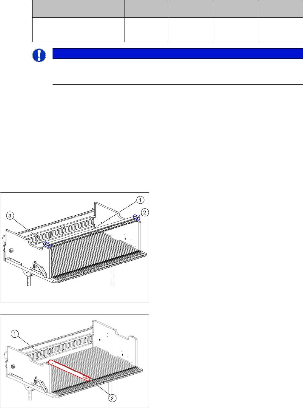
► On the original feeder locking bar (1), remove the
screws in positions (2) and (3).
► Remove the feeder locking bar.
1. Original guide profile removed
2. Installation location for the locking bar mount
► In the marked area (1), remove the original guide pro-
file.