00197961-01_UM_JTF-MW_on_SIPLACE_E_en - 第44页
Tasks on the Machine Loading and Unloading Trays 44 User Manual JTF-MW on SIPLACE E The latch mechanism o f the door is unlocked (1) . ► Open the door (1) . ► Pull the tray carrier out. ► Place the JEDEC trays (2) onto t…
Tasks on the Machine
Loading and Unloading Trays
User Manual JTF-MW on SIPLACE E 43
5.3
5.3 Loading and Unloading Trays
Loading and Unloading Trays
The tray magazine is installed in the JTF-MW tower.
LED indicators
Green LED – READY (1)
LED on Shows that a tray was successfully moved to the pick position and
is now ready for components to be removed from the tray (or for it
to be loaded). The LED also shows that a ready signal has been
sent to the host. As soon as the tray leaves the pick position, the
LED will extinguish.
LED off Not ready for loading or unloading or tray changeover.
Orange LED – Stop/Error (2)
LED on Stop condition. For example, occurs after stop button was pressed.
LED flashes Error condition. An error occurred during the tray changeover.
LED off Normal mode
Yellow LED – Inhibit (3)
LED on The yellow LED shows a lock. The feeder will not receive any tray
changeover commands, neither via the remote control nor manual-
ly.
LED off Normal mode.
Blue LED – Full/Empty (4) If the next tray is manually queried after the last tray in the maga-
zine (slot with the highest number), the blue LED will show EMPTY.
This also occurs when there is no magazine inserted.
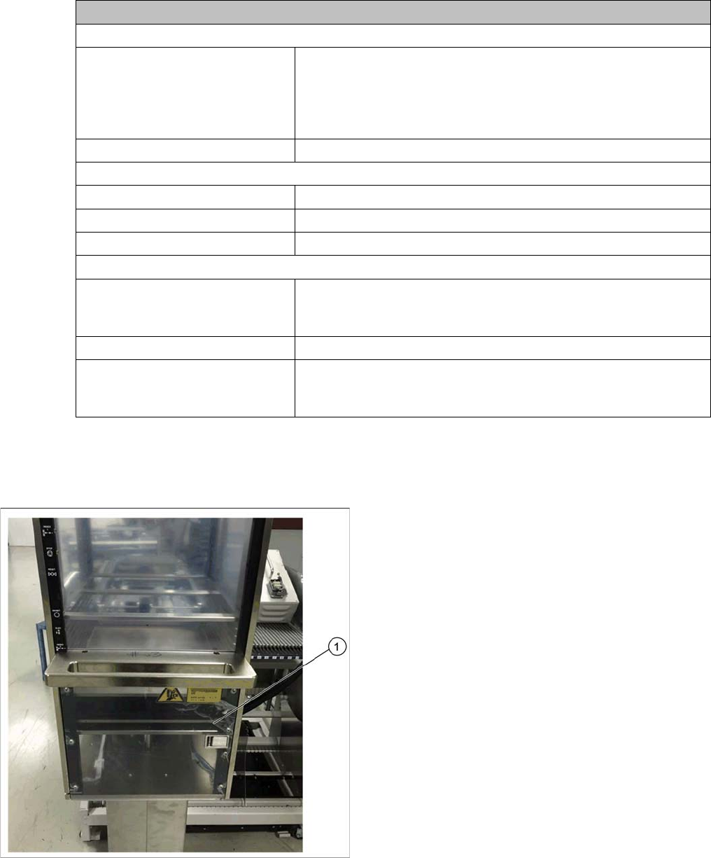
► Move the magazine down to the bottom limit (1).
Tasks on the Machine
Loading and Unloading Trays
44 User Manual JTF-MW on SIPLACE E
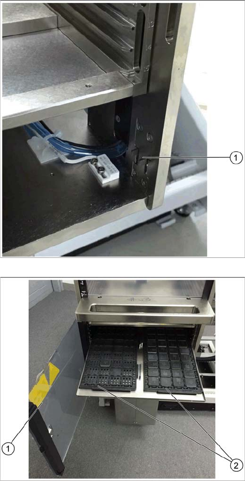
The latch mechanism of the door is unlocked (1).
► Open the door (1).
► Pull the tray carrier out.
► Place the JEDEC trays (2) onto the tray carrier.
► Close the door (1).
Tasks on the Machine
Setting the JEDEC Tray Delay
User Manual JTF-MW on SIPLACE E 45
5.4
5.4 Setting the JEDEC Tray Delay
Setting the JEDEC Tray Delay
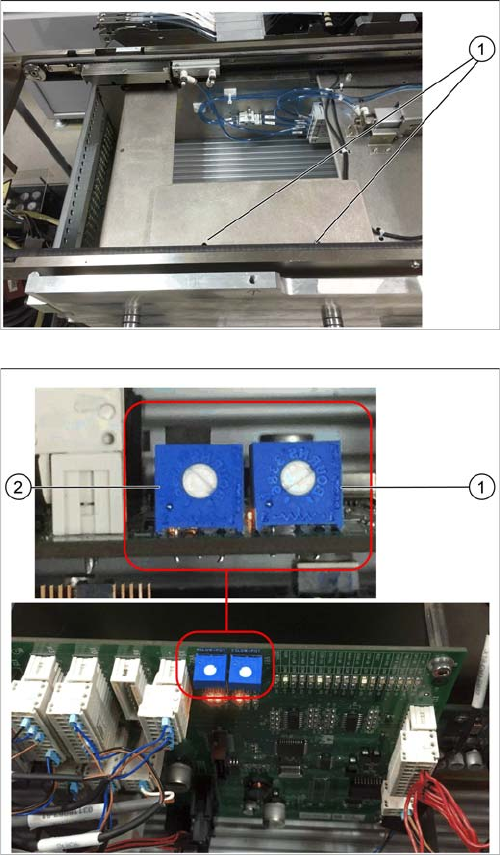
The JEDEC tray delay is adjusted by two potentiometers on the control board.
► Open the cover above the control board by loosening
the two screws (1).
1. Potentiometer for setting the speed of the forward
slow down sensor
2. Potentiometer for setting the speed of the return slow
down sensor
The factory setting for both potentiometers is 6. This set-
ting should not be changed.
► Ensure that the potentiometers are set to 6.
► Replace the cover.