00197469-02_SM_Twin_Kunde_EN.pdf - 第18页
3 Return unit 3.1 Replacing the return unit buffer 18 Service Manual SIPLACE TwinStar (Twin, Twin HF, Twin VHF) 07/2020 Installation Fig.12: Fitting the buffer (example of Twin / Twin HF shown) ► Screw the new buffer (2…
3 Return unit
3.1 Replacing the return unit buffer
Service Manual SIPLACE TwinStar (Twin, Twin HF, Twin VHF) 07/2020 17
3 Return unit
3.1 Replacing the return unit buffer
Parts
●
Select the required spare part:
Head type Spare part
Twin VHF module [03096701‑xx] Return unit buffer assembly VHF
[03091163‑xx]
Pick&Place module High Force R2
[03097486‑xx]
Return unit buffer assembly [03004759-xx]
Pick&Place module THK R2 [03097485‑xx]
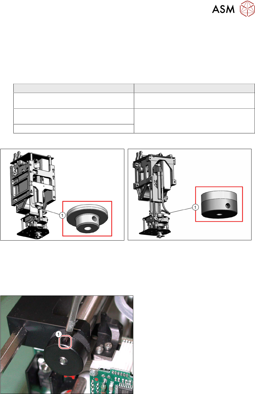
Overview
Fig.9: Return unit buffer assembly VHF [03091163‑xx]
Fig.10: Return unit buffer assembly [03004759-xx]
Preparation
► Remove the head from the machine. For details about removing and fitting the placement
head, refer to the service manual for your machine.
Removal
Fig.11: Dismantling the buffer (example of Twin / Twin HF
shown)
► Loosen the side grub screw(1) on the
buffer.
► Unscrew and remove the buffer.
3 Return unit
3.1 Replacing the return unit buffer
18 Service Manual SIPLACE TwinStar (Twin, Twin HF, Twin VHF) 07/2020
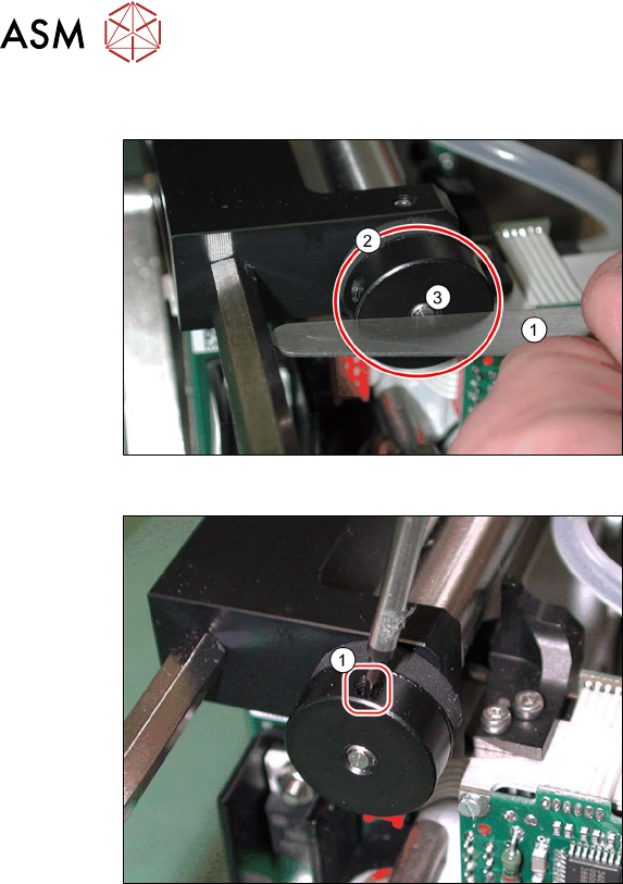
Installation
Fig.12: Fitting the buffer (example of Twin / Twin HF shown)
► Screw the new buffer (2)in until the un-
derside is level with the screw (3)
.
Check this e.g with a feeler gauge (1)
.
Fig.13: Fixing the buffer (example of Twin / Twin HF shown)
► Fix the buffer into place with the side
grub screw(1)
.
– Twin VHF: torque 0.3Nm
– Twin / Twin HF: hand-tighten
3 Return unit
3.2 Replacing the Z axis return unit
Service Manual SIPLACE TwinStar (Twin, Twin HF, Twin VHF) 07/2020 19
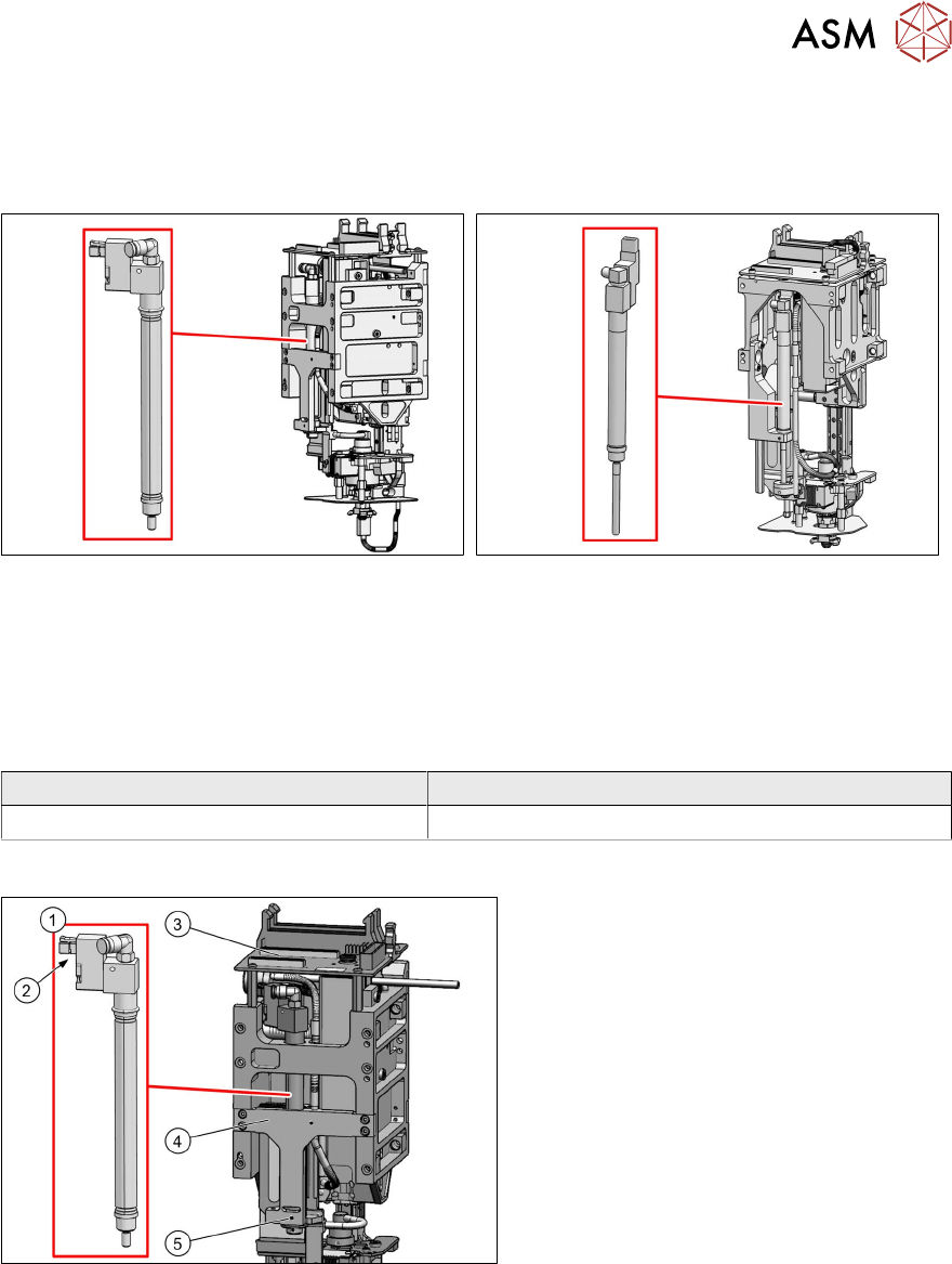
3.2 Replacing the Z axis return unit
Read the relevant chapter for details:
Twin VHF
Fig.14: Return unit VHF Twin [03101743‑xx]
Twin/Twin HF
Fig.15: Z axis return unit [03001361-xx]
For more information, read section 3.2.1 "Return
unit on the Twin VHF" [}19].
For more information, read section 3.2.2 "Return
unit on the Twin/Twin HF" [}21].
3.2.1 Return unit on the Twin VHF
Parts
Head type Spare part
Twin VHF module [03096701‑xx] Return unit VHF Twin [03101743‑xx]
Overview
Fig.16: Overview of return unit (example of Twin HF shown)
1. Return unit
2. Connector/coupling
3. Head main board
4. Mount
5. Grub screw on the mount
Preparation
► Remove the head from the machine. For details about removing and fitting the placement
head, refer to the service manual for your machine.