00197469-02_SM_Twin_Kunde_EN.pdf - 第57页
4 Pneumatic and pressure control valve (PRV) 4.8 Replacing the force measuring unit and the trick and feather unit Service Manual SIPLACE TwinStar (Twin, Twin HF, Twin VHF) 07/2020 57 Fig.99: Screws fastening the force …
4 Pneumatic and pressure control valve (PRV)
4.8 Replacing the force measuring unit and the trick and feather unit
56 Service Manual SIPLACE TwinStar (Twin, Twin HF, Twin VHF) 07/2020
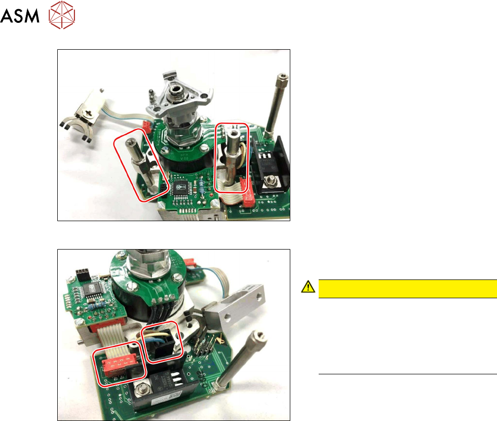
Fig.97: Spacer
► Remove the two spacers.
Fig.98: Connector
► Disconnect the incremental encoder
and the D axis.
CAUTION!
Do not damage the D axis connec-
tion!
The connector on the D axis cable is
easily damaged.
Carefully take off the connector. The
solder points could be easily damaged.
.
4 Pneumatic and pressure control valve (PRV)
4.8 Replacing the force measuring unit and the trick and feather unit
Service Manual SIPLACE TwinStar (Twin, Twin HF, Twin VHF) 07/2020 57
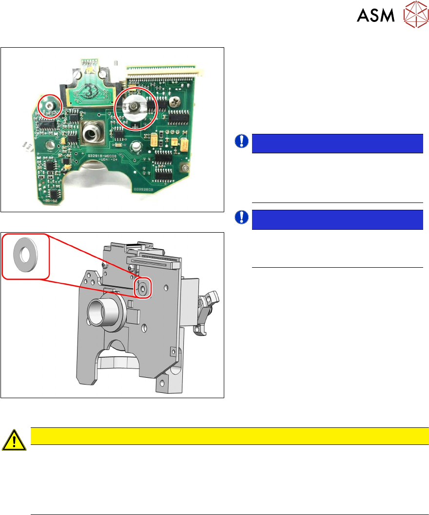
Fig.99: Screws fastening the force measuring unit
Fig.100: Washer
► Hold the rotary unit securely.
► Remove the left screw.
► Remove the righthand screw in the
pipe clamp.
► Take the force measuring unit off the
trick and feather unit.
NOTICE!
Plastic washer!
Take care not to lose the plastic
washer. This is located under the pipe
clamp.
.
NOTICE!
Third spacer!
If you are replacing the force measur-
ing unit, dismantle the third spacer.
.
CAUTION
Do not damage the incremental disk!
The incremental disk is now unprotected and could be easily damaged or contaminated.
► Handle the trick and feather unit with care so that the incremental disk is not dam-
aged.
► Keep the incremental disk clean.
4 Pneumatic and pressure control valve (PRV)
4.8 Replacing the force measuring unit and the trick and feather unit
58 Service Manual SIPLACE TwinStar (Twin, Twin HF, Twin VHF) 07/2020
4.8.3 Assembly
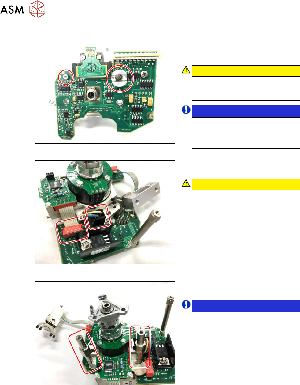
Fig.101: Screws fastening the force measuring unit
► Fasten the force measuring unit to the
trick and feather unit.
Hand-tighten the two fastening screws.
CAUTION!
Risk of short circuit!
Make sure that you fit the plastic
washer under the pipe holder.
.
NOTICE!
Pipe holder!
Align the slit in the pipe holder so that
it is parallel to the edge of the printed
circuit board.
.
Fig.102: Connector
► Disconnect the incremental encoder
and the D axis motor.
CAUTION!
Do not damage the D axis connec-
tion!
The connector on the D axis cable is
easily damaged.
Plug in the connector with care. The
solder points could be easily damaged.
.
Fig.103: Spacer
► Fit the two spacers with the short sides
facing upwards and hand-tighten these.
NOTICE!
Third spacer!
If you are replacing the force measur-
ing unit, fit the third spacer.
.