00197469-02_SM_Twin_Kunde_EN.pdf - 第60页
4 Pneumatic and pressure control valve (PRV) 4.8 Replacing the force measuring unit and the trick and feather unit 60 Service Manual SIPLACE TwinStar (Twin, Twin HF, Twin VHF) 07/2020 Fig.107: Force transducer ► Fit the…
4 Pneumatic and pressure control valve (PRV)
4.8 Replacing the force measuring unit and the trick and feather unit
Service Manual SIPLACE TwinStar (Twin, Twin HF, Twin VHF) 07/2020 59
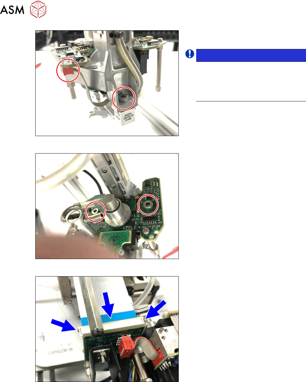
Fig.104: Grub screw for fly wheel
► Fit the fly wheel and fix into place with
the two grub screws.
Fig.105: Fitting the rotary unit
► Fit the rotary unit to the Z axis shaft
and hand-tighten the two screws.
CAUTION!
Do not damage the incremental
disk!
The incremental disk is now access-
ible, down at the rotary unit.
Handle the rotary unit with care. The
incremental disk can be easily dam-
aged or contaminated.
.
Fig.106: Z axis motor connector
► Connect the Z axis motor.
4 Pneumatic and pressure control valve (PRV)
4.8 Replacing the force measuring unit and the trick and feather unit
60 Service Manual SIPLACE TwinStar (Twin, Twin HF, Twin VHF) 07/2020
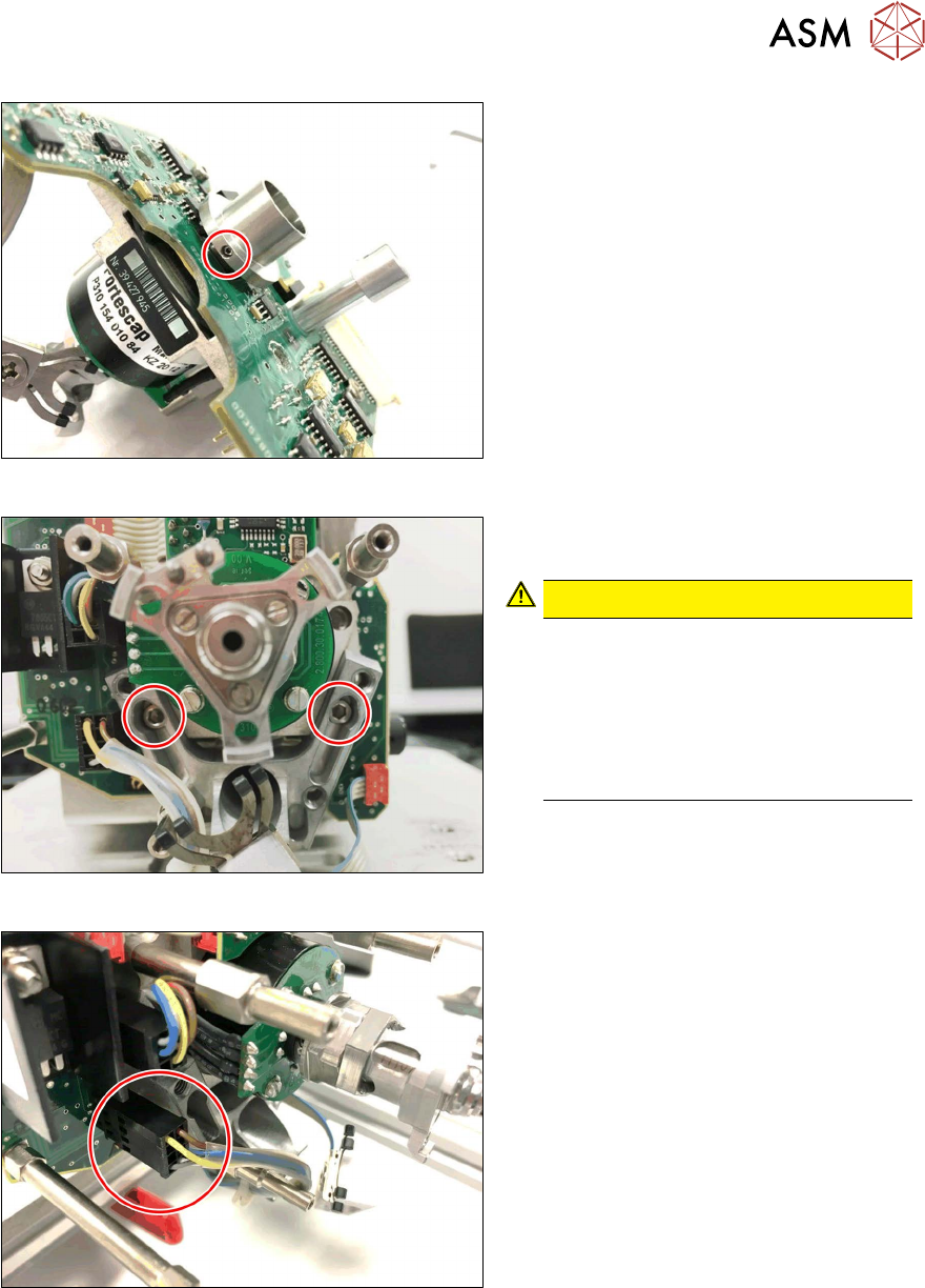
Fig.107: Force transducer
► Fit the force transducer. Fix carefully
into place with a screw.
NOTICE!
Fit the adjustment wedge correctly!
The adjustment wedge has a curved
and a straight side.
Insert the adjustment wedge so that
the straight side faces the sensor.
.
Fig.108: Force measuring unit
► Fix the force measuring unit into place
with the two fastening screws (hand-
tight).
Fig.109: Connecting the control cable
► Connect the control cable and fix it with
the lock.
► Fit the hose guidance, the flat ribbon baffle and the stopper.
3.3 "Replacing the hose and flat ribbon guide (Twin HF only)" [}23]
► Fit the sleeve with ball fixing with a new seal.
4.6 "Replacing the sleeve with ball fixing/seal" [}43]
4 Pneumatic and pressure control valve (PRV)
4.8 Replacing the force measuring unit and the trick and feather unit
Service Manual SIPLACE TwinStar (Twin, Twin HF, Twin VHF) 07/2020 61
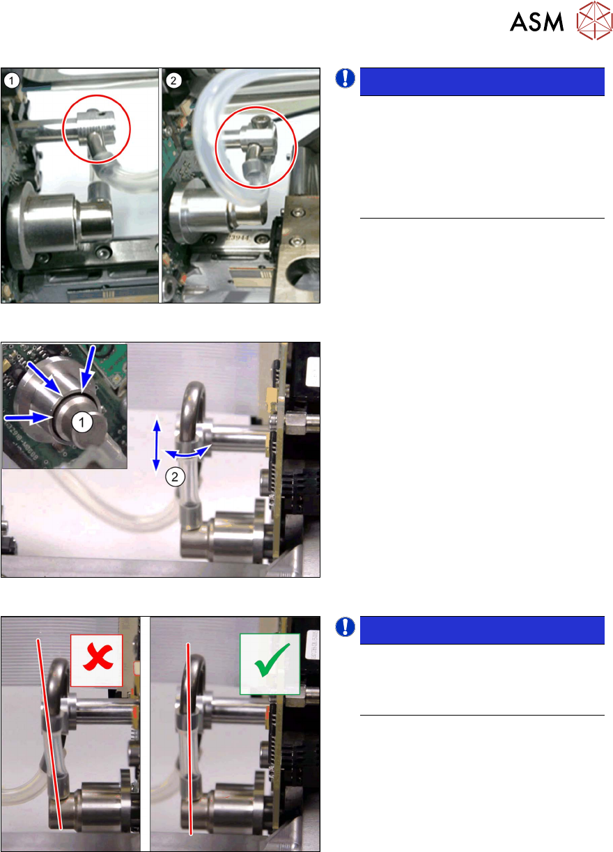
Fig.110: Holder and pipe clamp versions
NOTICE!
Different holder and pipe clamp ver-
sions!
There are two different versions of the
holder and pipe clamp. These are also
set differently.
(1) Old version (loose)
(2) New version (fixed)
.
Fig.111: Fitting the new holder and pipe clamp
New holder and pipe clamp
► Connect the hoses to the holder, pipe
clamp and rotary supply.
► Attach the holder and pipe clamp and
fix into place with a screw.
► Set the hose(2) so that this runs dir-
ectly between the rotary supply and the
holder plus pipe clamp.
► The rotary supply(1) must sit in the
center of the fly wheel without exerting
any side forces.
Fig.112: Check the new holder and pipe clamp
NOTICE!
Check the new holder and pipe
clamp!
Make sure that the hose runs parallel
to the pipes.
.