00197469-02_SM_Twin_Kunde_EN.pdf - 第65页
5 Boards and cables 5.1 Replacing the head main board Service Manual SIPLACE TwinStar (Twin, Twin HF, Twin VHF) 07/2020 65 5 Boards and cables See also 2 3.3 "Replacing the hose and flat ribbon guide (Twin HF only)&…
4 Pneumatic and pressure control valve (PRV)
4.8 Replacing the force measuring unit and the trick and feather unit
64 Service Manual SIPLACE TwinStar (Twin, Twin HF, Twin VHF) 07/2020
Fig.119: Fixing the dual rotating disk in place
► Carefully fix the dual rotating disk into
place with the counternut.
Use two open-end wrenches with a
wrench opening of 15mm.
► Repeat the measurement.
► To correct the setting, loosen the dual
rotating disk and the counternut.
► Repeat this process until the measure-
ment is ok.
5 Boards and cables
5.1 Replacing the head main board
Service Manual SIPLACE TwinStar (Twin, Twin HF, Twin VHF) 07/2020 65
5 Boards and cables
See also
2 3.3 "Replacing the hose and flat ribbon guide (Twin HF only)" [}23]
5.1 Replacing the head main board
Parts
Select the required spare part:
Head type Spare part
Twin VHF module [03096701‑xx] Head main board VHF-Twin [03104106‑xx]
Head main board P&P head [00352833-xx]
Pick&Place module High Force R2
[03097486‑xx]
Head main board P&P head [00352833-xx]
Pick&Place module THK R2 [03097485‑xx]
Overview
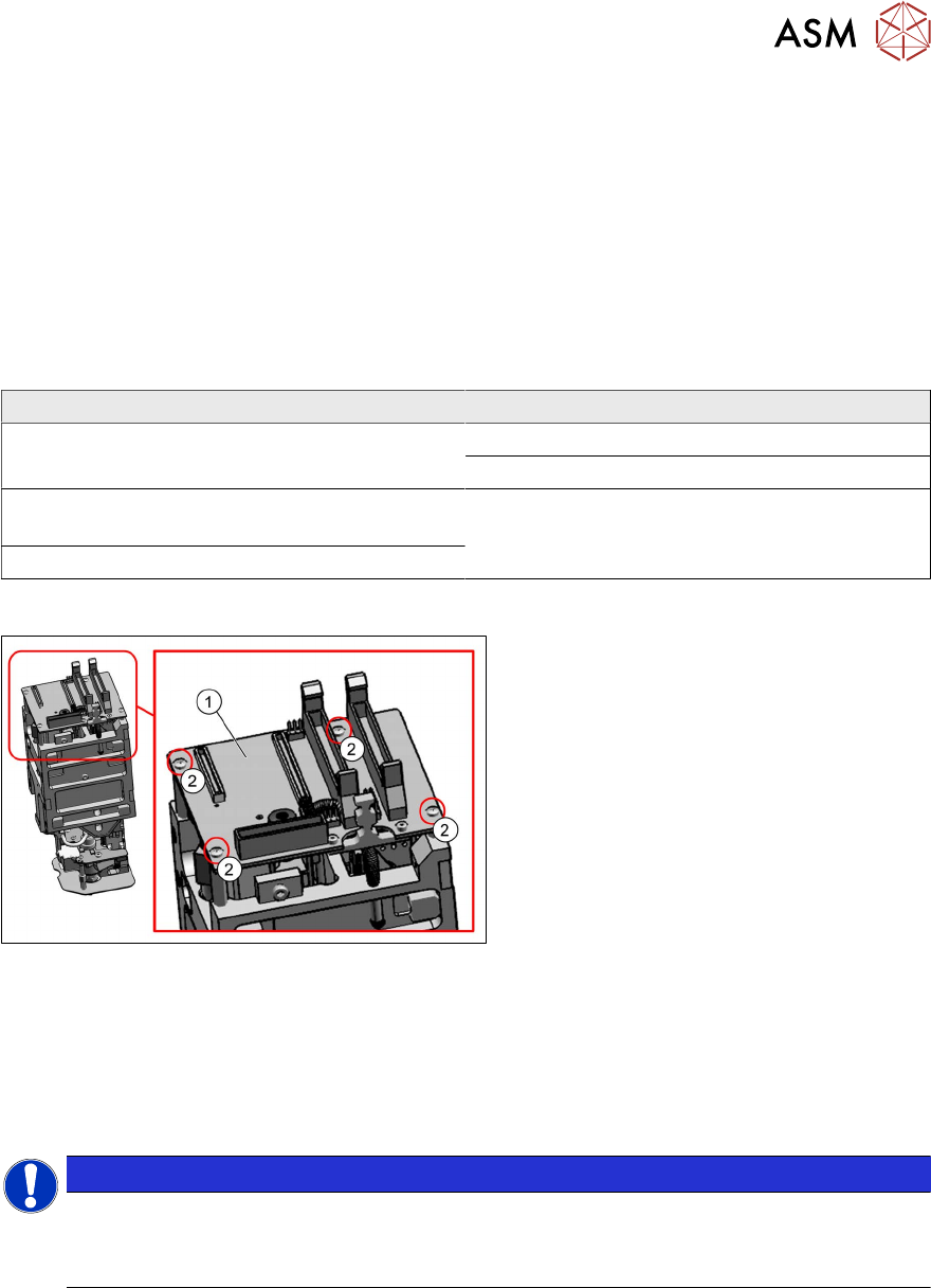
Fig.120: Head main board (example of Twin VHF shown)
1. Head main board
2. Four fastening screws with spacer
sleeves under the board
For more information about the head main
board, see section 5.1.1
"Head main board
C600" [}69].
Preparation
► Remove the head from the machine. For details about removing and fitting the placement
head, refer to the service manual for your machine.
Removal
NOTICE
Connectors
A number of connectors are unplugged during replacement work.
► Mark the position to make clear assignment easier later on.
► On Twin VHF only:
Dismantle the flat ribbon holder.
The connecting cable to the DP unit is plugged in at the underside of the head main board.
You need to remove the flat ribbon holder in order to lift up the board. The cable could other-
wise be damaged.
5.4 "Replacing the flat ribbon holder, Twin VHF (Twin VHF only)" [}75]
► Dismantle the strain relief.
5.7 "Replacing the strain relief for the Z encoder Twin" [}80]
► Loosen the screws fastening the PRV and pull this down. This releases the connector from
the PRV to the head main board.
4.2 "Replacing the pressure control valve (PRV)" [}27]
5 Boards and cables
5.1 Replacing the head main board
66 Service Manual SIPLACE TwinStar (Twin, Twin HF, Twin VHF) 07/2020
► Unplug all electrical connections to the head main board. If necessary, mark their positions to
make clear assignment easier later on.
– Two flat ribbon cable connectors from the Twin module to the gantry
– One connector for the return cylinder
– One connector for the incremental encoder Z axis (incl. strain relief)
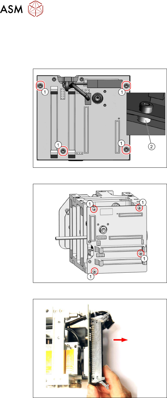
Fig.121: Fastening screws
► Twin / Twin VHF only:
Remove the four fastening screws(1).
Take care not to lose the four spacer
sleeves (2)
under the board. These can
be grasped and removed with a small
Allen key.
Fig.122: Fastening screws for head main board
► Twin VHF only:
Remove the four fastening screws(1).
Fig.123: Screws fastening the head main board (example of
Twin VHF shown)
► Carefully pull off the head main board.
This also disconnects the supply plug
on the vacuum generator.
Take care of the control cable on the
underside (see below).