00197469-02_SM_Twin_Kunde_EN.pdf - 第67页
5 Boards and cables 5.1 Replacing the head main board Service Manual SIPLACE TwinStar (Twin, Twin HF, Twin VHF) 07/2020 67 Fig.124: Disconnecting the control cable (example of Twin / TwinHF shown) ► Release the connect…
5 Boards and cables
5.1 Replacing the head main board
66 Service Manual SIPLACE TwinStar (Twin, Twin HF, Twin VHF) 07/2020
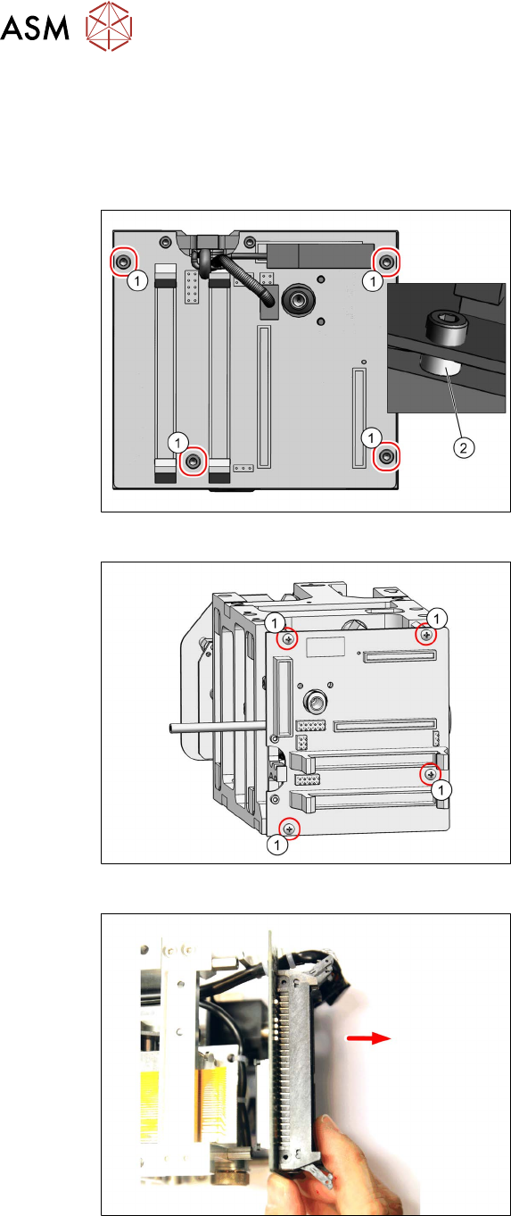
► Unplug all electrical connections to the head main board. If necessary, mark their positions to
make clear assignment easier later on.
– Two flat ribbon cable connectors from the Twin module to the gantry
– One connector for the return cylinder
– One connector for the incremental encoder Z axis (incl. strain relief)
Fig.121: Fastening screws
► Twin / Twin VHF only:
Remove the four fastening screws(1).
Take care not to lose the four spacer
sleeves (2)
under the board. These can
be grasped and removed with a small
Allen key.
Fig.122: Fastening screws for head main board
► Twin VHF only:
Remove the four fastening screws(1).
Fig.123: Screws fastening the head main board (example of
Twin VHF shown)
► Carefully pull off the head main board.
This also disconnects the supply plug
on the vacuum generator.
Take care of the control cable on the
underside (see below).
5 Boards and cables
5.1 Replacing the head main board
Service Manual SIPLACE TwinStar (Twin, Twin HF, Twin VHF) 07/2020 67
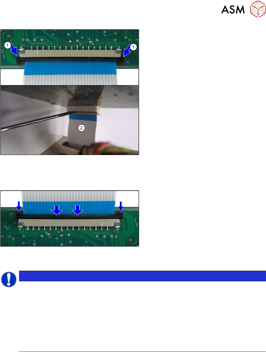
Fig.124: Disconnecting the control cable (example of Twin /
TwinHF shown)
► Release the connector lock on the con-
trol cable(1)
.
► (2) Use a screwdriver to lever the con-
nector lock very carefully
out.
Incorrect handling could cause the
cable clamp to break.
Installation
Fig.125: Attaching the control cable (example of Twin /
TwinHF shown)
► Connect the new control cable to the
head main board.
Pull up the connector fixtures or put in
a new connector fixtures.
Insert the control cable until the con-
tacts fully engage.
NOTICE
Connector fixtures
Observe the correct installation position of the control cable.
Carefully press in the connector fixtures.
The connector lock may not protrude upwards in the center.
The locking bracket must be mounted straight and click into place tightly. If the locking
bracket is mounted at an angle, it might break.
► Spare parts:
In the event of cable damage see5.5
"Replacing the control cable" [}76]:
In the event of bracket damage: locking bracket SAMTEC [03104052-xx]
► Press the two locking handles down. The control cable should now sit firmly on the connector
plug.
► Push the PRV upwards and tighten the fastening screws.
5 Boards and cables
5.1 Replacing the head main board
68 Service Manual SIPLACE TwinStar (Twin, Twin HF, Twin VHF) 07/2020
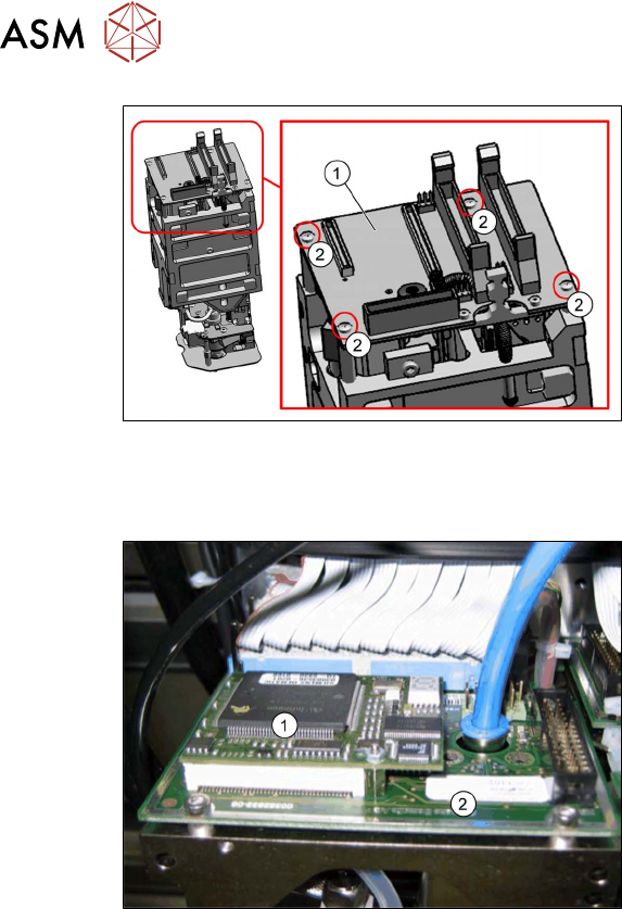
Fig.126: Head main board (example of Twin VHF shown)
► Carefully attach the new head main
board(1)
. This also reconnects the
vacuum generator.
► Fit the fastening screws (2) (with the
spacer sleeves for Twin /Twin HF).
► Reestablish all connections to the elec-
tricity supply.
Follow the removal instructions in reverse order for further installation. Also observe the following
instructions:
Fig.127: TQM module on the head main board (example of
Twin / Twin HF shown)
1. TQM167 SIPLACE Embedded Module
[03003536‑xx] (can also be ordered as
a spare part)
2. Head main board
A TQM module could be located on the
head main board when operating older
machines.
► If a TQM module was fitted to an older
head, fit this to the head main board of
the new head.
► Observe the installation instructions in the following sections:
5.7 "Replacing the strain relief for the Z encoder Twin" [}80]
5.5 "Replacing the control cable" [}76]
5.4 "Replacing the flat ribbon holder, Twin VHF (Twin VHF only)" [}75]
► Transfer the head data to the machine data at the station.