00197469-02_SM_Twin_Kunde_EN.pdf - 第69页
5 Boards and cables 5.1 Replacing the head main board Service Manual SIPLACE TwinStar (Twin, Twin HF, Twin VHF) 07/2020 69 5.1.1 Head main board C600 Fig.128: Head main board C600 [00352833-xx] LEDs [00352833-09] LED Co…
5 Boards and cables
5.1 Replacing the head main board
68 Service Manual SIPLACE TwinStar (Twin, Twin HF, Twin VHF) 07/2020
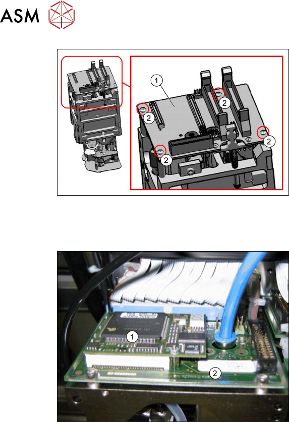
Fig.126: Head main board (example of Twin VHF shown)
► Carefully attach the new head main
board(1)
. This also reconnects the
vacuum generator.
► Fit the fastening screws (2) (with the
spacer sleeves for Twin /Twin HF).
► Reestablish all connections to the elec-
tricity supply.
Follow the removal instructions in reverse order for further installation. Also observe the following
instructions:
Fig.127: TQM module on the head main board (example of
Twin / Twin HF shown)
1. TQM167 SIPLACE Embedded Module
[03003536‑xx] (can also be ordered as
a spare part)
2. Head main board
A TQM module could be located on the
head main board when operating older
machines.
► If a TQM module was fitted to an older
head, fit this to the head main board of
the new head.
► Observe the installation instructions in the following sections:
5.7 "Replacing the strain relief for the Z encoder Twin" [}80]
5.5 "Replacing the control cable" [}76]
5.4 "Replacing the flat ribbon holder, Twin VHF (Twin VHF only)" [}75]
► Transfer the head data to the machine data at the station.
5 Boards and cables
5.1 Replacing the head main board
Service Manual SIPLACE TwinStar (Twin, Twin HF, Twin VHF) 07/2020 69
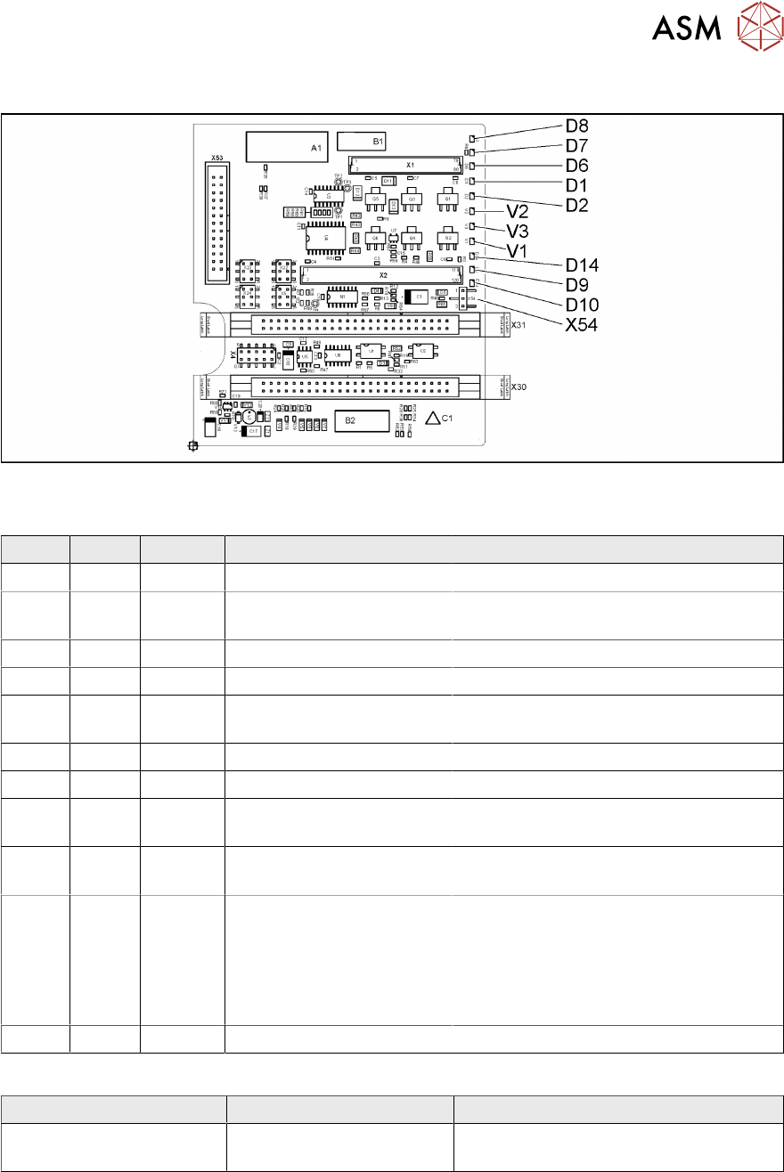
5.1.1 Head main board C600
Fig.128: Head main board C600 [00352833-xx]
LEDs [00352833-09]
LED Color Status Signal name Description
D1 YE OFF Z_PRESSURE Not used
D2 YE ON/OFF Z_CLAMPING ON: Z axis clamping activated
OFF: return unit in upper position
D6 GN OFF Z_REFERENCEBERO Not used
D7 GN ON - Return cylinder moved out
D8 GN OFF Q3_OUT Flashes shortly when the return unit is
moved out
D9 GN OFF Q1_OUT Not used
D10 GN ON VCC_PROPVALVE +24VDC for vacuum generator OK
D14 RD OFF SPI_PROP_VALVE_ALAR
M_N
ON: vacuum generator defective
V1 GN ON Z_TEMPERATURE-
SENSOR
Z motor temperature OK
V2 GN ON/OFF V_OUT Signalizes the 15V power supply for the
D axes track signals
OFF: Jumper X54 set to ON for the old
force measuring board
ON: Jumper X54 set to OFF for the new
force measuring board
V3 GN ON V_OUT +15VDC for the D axes track signals
Jumper [00352833-09]
Jumper Status Description
X54 OFF New force measuring board: LED V2
ON
5 Boards and cables
5.1 Replacing the head main board
70 Service Manual SIPLACE TwinStar (Twin, Twin HF, Twin VHF) 07/2020
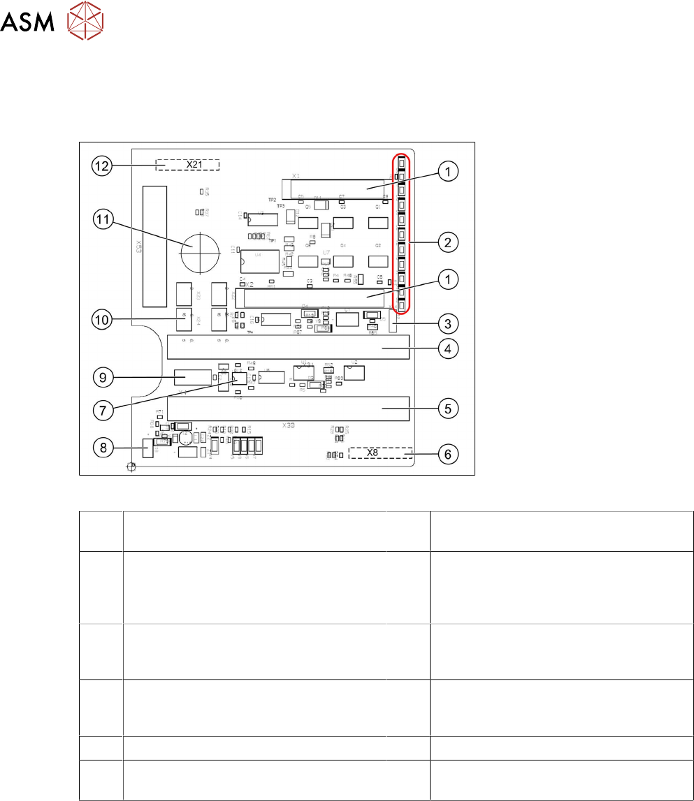
Further information
The head main board is mounted directly on the P&P module. The head main board is connected
to the basis adapter (SIPLACE SX/DX-Series) or head adapter (SIPLACE X‑Series) with two flat
ribbon cables.
Fig.129: Head main board C600 [00352833-xx]
1 Two connectors for the 16 bit CAN bus
processor (not used for X/D1/D3)
2 LEDs (see below)
3 X54 jumper
currently set to ON
with the new force measuring board set
to OFF (see LED V2/V_SP)
4 Connector to the head adapter flat rib-
bon cable
5 Connector to the head adapter flat rib-
bon cable
6 X8: Flex cable (signals: track signals D
axis, motor voltage Z axis/D axis, Z tem-
perature, SPI bus)
7 EEPROM stores the head specific data
(head exchange, reference run)
8 Power supply 15 V for the D axis track
signals (currently deactivated via the
jumper)
9 X4: connector track signals Z axis 10 Connector pneumatic valve (retract unit)
11 Hole for pneumatic hose to the vacuum
generator
12 X21: connector for vacuum generator