00197469-02_SM_Twin_Kunde_EN.pdf - 第71页
5 Boards and cables 5.1 Replacing the head main board Service Manual SIPLACE TwinStar (Twin, Twin HF, Twin VHF) 07/2020 71 To (2) LEDs (description sequence downwards) LED Color Description D8 Green Off – return unit is …
5 Boards and cables
5.1 Replacing the head main board
70 Service Manual SIPLACE TwinStar (Twin, Twin HF, Twin VHF) 07/2020
Further information
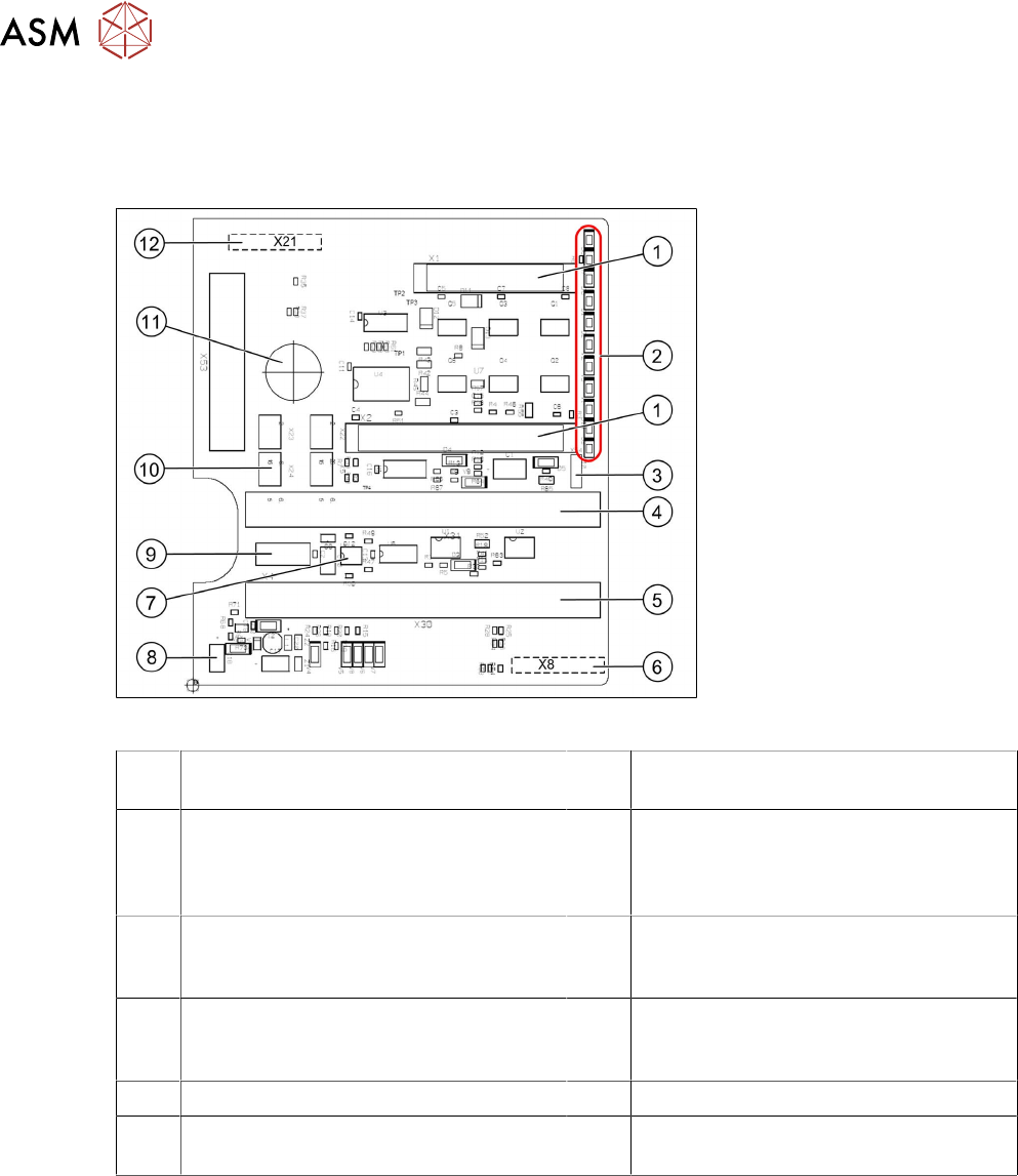
The head main board is mounted directly on the P&P module. The head main board is connected
to the basis adapter (SIPLACE SX/DX-Series) or head adapter (SIPLACE X‑Series) with two flat
ribbon cables.
Fig.129: Head main board C600 [00352833-xx]
1 Two connectors for the 16 bit CAN bus
processor (not used for X/D1/D3)
2 LEDs (see below)
3 X54 jumper
currently set to ON
with the new force measuring board set
to OFF (see LED V2/V_SP)
4 Connector to the head adapter flat rib-
bon cable
5 Connector to the head adapter flat rib-
bon cable
6 X8: Flex cable (signals: track signals D
axis, motor voltage Z axis/D axis, Z tem-
perature, SPI bus)
7 EEPROM stores the head specific data
(head exchange, reference run)
8 Power supply 15 V for the D axis track
signals (currently deactivated via the
jumper)
9 X4: connector track signals Z axis 10 Connector pneumatic valve (retract unit)
11 Hole for pneumatic hose to the vacuum
generator
12 X21: connector for vacuum generator
5 Boards and cables
5.1 Replacing the head main board
Service Manual SIPLACE TwinStar (Twin, Twin HF, Twin VHF) 07/2020 71
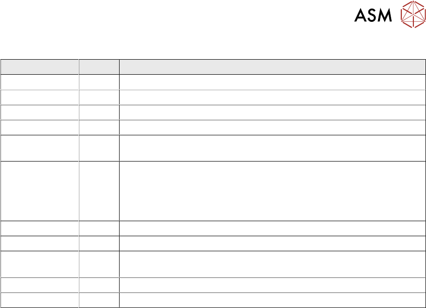
To (2) LEDs (description sequence downwards)
LED Color Description
D8 Green Off – return unit is moved out – LED shines briefly
D7 CLAMP Green On - display showing that the return cylinder has been moved out.
D6 BERO Green Off - without function (previously: proximity switch, Z axis top)
D1 PRESSURE Yellow Off - without function (Z pressure)
D2 CLAMP Yellow On – Z axis clamping
Off – return unit is in "top position"
V2/V_SP Green Shows the 15V power supply for the D axis track signals.
Off – when jumper setting is ON and with old force measuring board.
On – when TwinHead has new force measuring board, the 15V is
regulated on the head main board i.e. the jumper must be set to OFF
and the LED is on.
V3 15V_ Green On – 15V for the D axis track signals
V1 TEMP Green On - Z axis motor temperature is OK
D14 ALARM Red Off - Alarm output for the vacuum generator
On - Vacuum generator defective
D9 PRESSURE Green Off - without function (Z pressure)
D10 24V+ Green On – 24V for vacuum generator OK
5 Boards and cables
5.2 Transferring the head specific data
72 Service Manual SIPLACE TwinStar (Twin, Twin HF, Twin VHF) 07/2020
5.2 Transferring the head specific data
CAUTION
Observe the direction of transfer!
After replacing the PRV, you need to send the valid machine data from the machine to the
new assembly.
The data only needs to be sent from the head to the machine if you have replaced the en-
tire module.
ü As the buttons required are very near to each other, take care that you do not acci-
dentally press the wrong one on the touch screen!
► Make sure you press the correct arrow button. To be on the safe side, select the but-
ton with the mouse.
ð The following section shows the transfer from the machine to the assembly.
► From software version 601 read the section Transmitting the Head-Specific Data (from
SW601).
► From software version 701 read the section Transferring the Head-Specific Data (from
SW701).
5.2.1 Transmitting the head-specific data (from SW601)
► Select the Settings → Access level… menu….
► Switch over to the operating level Service and select OK.
► Start the SITEST program .
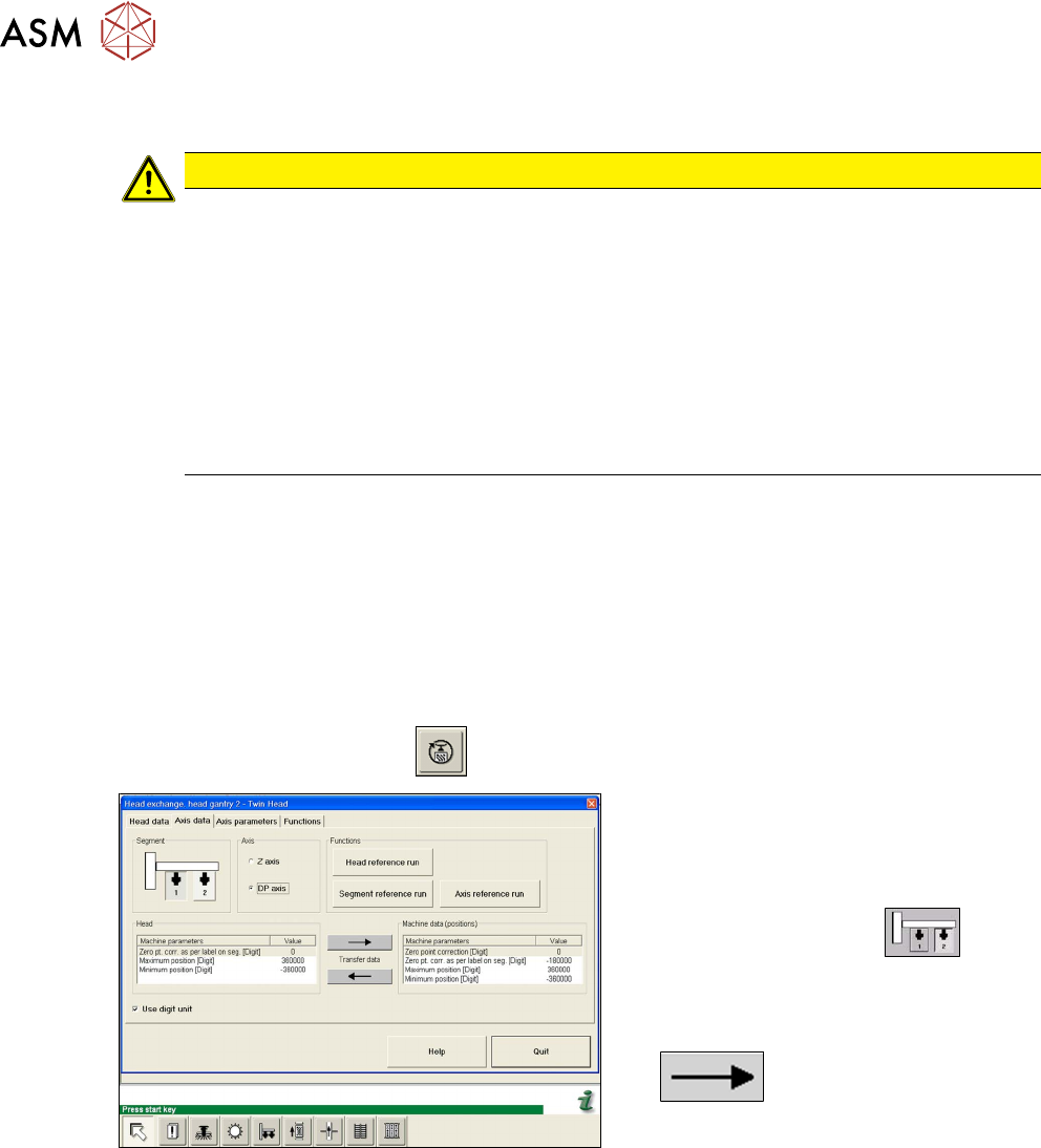
Fig.130: Transmitting the DP axis data
► Select the Settings:head ex-
change:head gantry menu for the rel-
evant gantry.
► Select the Axis data tab.
► Select the Twin module.
► Select the DP axis.
► Transfer the machine data from the
head to the machine data, with the
button.
► Select Close.