00197469-02_SM_Twin_Kunde_EN.pdf - 第78页
5 Boards and cables 5.5 Replacing the control cable 78 Service Manual SIPLACE TwinStar (Twin, Twin HF, Twin VHF) 07/2020 Installation ► Fit the head main board. 5.1 "Replacing the head main board" [ } 65] Fig.…
5 Boards and cables
5.5 Replacing the control cable
Service Manual SIPLACE TwinStar (Twin, Twin HF, Twin VHF) 07/2020 77
Fig.137: Stopper for return unit and flat ribbon baffle (exam-
ple of Twin / TwinHF shown)
1. Stopper for return unit
2. Return unit buffer assembly
3. Flat ribbon baffle
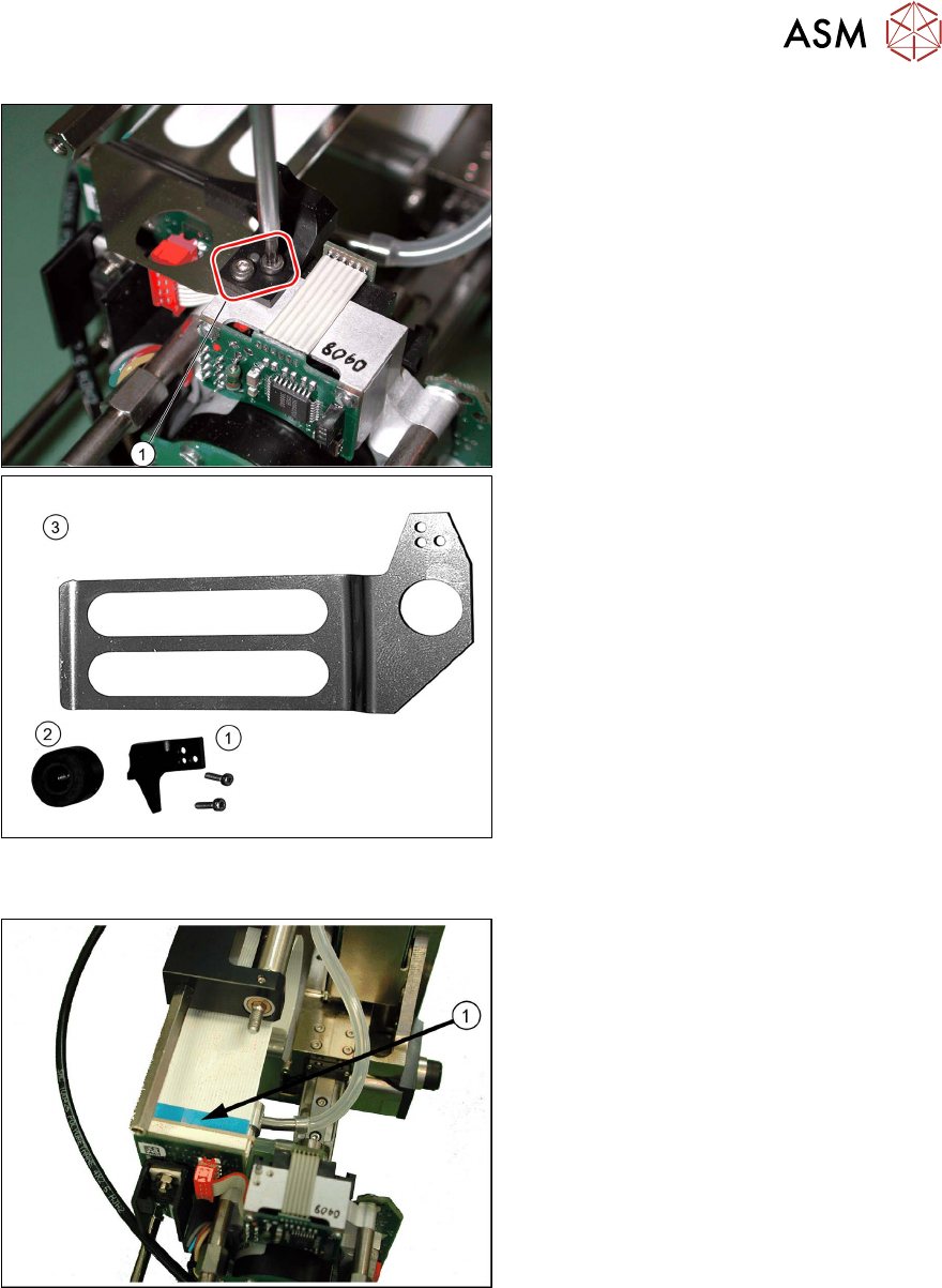
► Remove the two screws fastening the
stopper(1)
for the return unit.
► Remove the flat ribbon baffle(3).
See also 3.3
"Replacing the hose and
flat ribbon guide (Twin HF only)" [}23]
Fig.138: Removing the control cable (example of Twin /
TwinHF shown)
► Release the two locking levers on the
connector upwards and pull the control
cable(1)
carefully off the force meas-
urement board.
► Remove the control cable from the
placement head.
5 Boards and cables
5.5 Replacing the control cable
78 Service Manual SIPLACE TwinStar (Twin, Twin HF, Twin VHF) 07/2020
Installation
► Fit the head main board.
5.1 "Replacing the head main board" [}65]
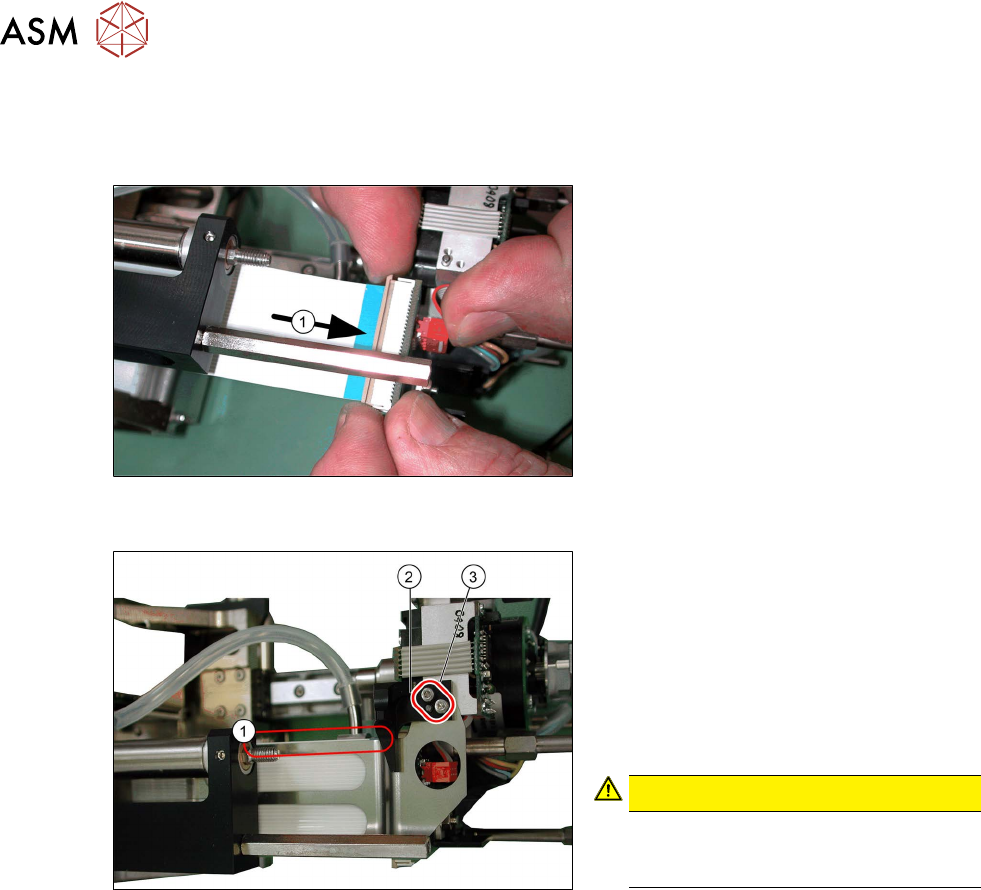
Fig.139: Attaching the control cable (example of Twin /
TwinHF shown)
► Reconnect the control cable to the
force measuring board(1)
.
Fig.140: Fitting the flat ribbon baffle and stopper for the re-
turn unit (example of Twin / TwinHF shown)
► Place the flat ribbon baffle on to the
control cable.
► Place the return unit stopper (2) onto
the flat ribbon baffle.
► Insert the two screws(3) into the return
unit stopper.
► Align the flat ribbon baffle to the control
cable.
CAUTION!
The flat ribbon baffle and control
cable must run parallel to one an-
other(1)!
.
Follow the removal instructions in reverse order for further installation.
Also observe the installation instructions in the following section:
3.1 "Replacing the return unit buffer" [}17]
5 Boards and cables
5.6 Replacing the connector clamping piece
Service Manual SIPLACE TwinStar (Twin, Twin HF, Twin VHF) 07/2020 79
5.6 Replacing the connector clamping piece
Parts
●
Clamping piece for connector [03005851‑xx] (suitable for all Twin types)
Overview
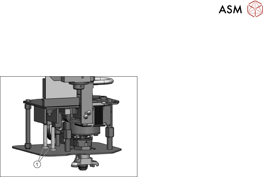
Fig.141: Connector clamping piece
1. Clamping piece for connector
[03005851‑xx] (two per head)
●
Fastening screw [03013039‑xx]
(on the underside of the lens hood)
DIN EN ISO7380-M2.5x5-10.9, black
zinc
Preparation
► Remove the head from the machine. For details about removing and fitting the placement
head, refer to the service manual for your machine.
Removal
► Remove the screw fastening the clamping piece on the underside of the lens hood and
remove the clamping piece.
Installation
Follow the removal instructions in reverse order for installation.