00197469-02_SM_Twin_Kunde_EN.pdf - 第80页
5 Boards and cables 5.7 Replacing the strain relief for the Z encoder Twin 80 Service Manual SIPLACE TwinStar (Twin, Twin HF, Twin VHF) 07/2020 5.7 Replacing the strain relief for the Z encoder Twin Parts ● Strain relief…
5 Boards and cables
5.6 Replacing the connector clamping piece
Service Manual SIPLACE TwinStar (Twin, Twin HF, Twin VHF) 07/2020 79
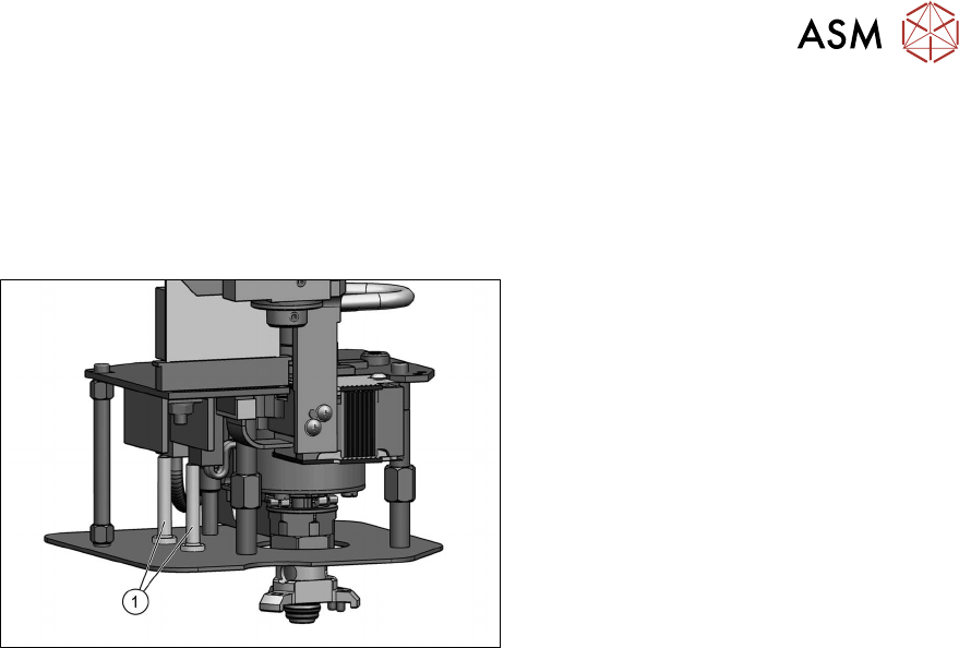
5.6 Replacing the connector clamping piece
Parts
●
Clamping piece for connector [03005851‑xx] (suitable for all Twin types)
Overview
Fig.141: Connector clamping piece
1. Clamping piece for connector
[03005851‑xx] (two per head)
●
Fastening screw [03013039‑xx]
(on the underside of the lens hood)
DIN EN ISO7380-M2.5x5-10.9, black
zinc
Preparation
► Remove the head from the machine. For details about removing and fitting the placement
head, refer to the service manual for your machine.
Removal
► Remove the screw fastening the clamping piece on the underside of the lens hood and
remove the clamping piece.
Installation
Follow the removal instructions in reverse order for installation.
5 Boards and cables
5.7 Replacing the strain relief for the Z encoder Twin
80 Service Manual SIPLACE TwinStar (Twin, Twin HF, Twin VHF) 07/2020
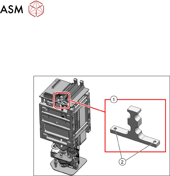
5.7 Replacing the strain relief for the Z encoder Twin
Parts
●
Strain relief Z encoder Twin [03098048‑xx] (suitable for all Twin types)
Overview
Fig.142: Strain relief Z encoder Twin [03098048‑xx] (exam-
ple of Twin VHF shown)
1. Strain relief Z encoder Twin
[03098048‑xx]
2. Two fastening screws for strain relief
Preparation
► Remove the head from the machine. For details about removing and fitting the placement
head, refer to the service manual for your machine.
Removal
► Remove the cable ties from the strain relief.
► Remove the two screws fastening the strain reliefand then remove the strain relief.
Installation
Follow the removal instructions in reverse order for installation.
6 Parameter and Calibrations
6.1 Parameters and calibrations SW7xx.x
Service Manual SIPLACE TwinStar (Twin, Twin HF, Twin VHF) 07/2020 81
6 Parameter and Calibrations
6.1 Parameters and calibrations SW7xx.x
► To calibrate with SW7xx.x, read the relevant section in the job cards for your machine or the
calibration manual, if available.
6.2 Parameters and calibrations SW6xx.x
6.2.1 Overview: Calibration Steps and Parameters
Requirement: the Twin module is fitted and con-
nected to the electrical and pneumatic systems.
Switch the machine on and start SITEST Note: Do not start a reference run
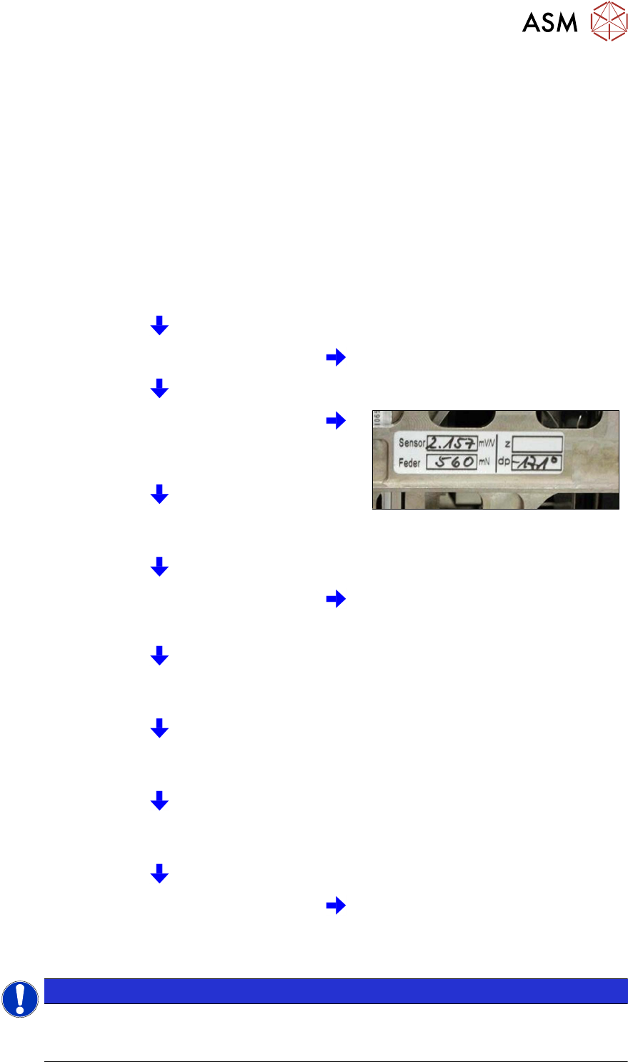
Parameters for the power sensor, spring pre-ten-
sion and possibly default values for the Z axis
(max./min. travel range and zero point correction)
enter zero point correction for DP axis.
Starting a reference run for the DP axis
Calibrating the DP axis
Calibration of the vacuum control system in the
Head board → Zero calibration for pressure
regulator menu
Requirement for further calibration:
overall reference run
Check the zero calibration in the Head board →
Measure pressure menu
Calibrate the closed vacuum in the TwinHead →
Calibration functions menu
Check the air blast pressure and vacuum system
tightness in the TwinHead → Head board
menu
Calibrate the TwinHead and nozzle changer in the
main menu at SITEST →
All heads and cameras
(Twin module only 1)
Note: the first garage n the nozzle
changer must be empty and the filling
level adjusted.
NOTICE
Initial setup, module replacement
These steps are necessary during the first initial setup or a replacement of the TwinHead
module. The detailed description can be found on the following pages.