00197469-02_SM_Twin_Kunde_EN.pdf - 第82页
6 Parameter and Calibrations 6.2 Parameters and calibrations SW6xx.x 82 Service Manual SIPLACE TwinStar (Twin, Twin HF, Twin VHF) 07/2020 6.2.2 Parameters for TwinHead Fig.143: Label with D axis correction value and par…
6 Parameter and Calibrations
6.1 Parameters and calibrations SW7xx.x
Service Manual SIPLACE TwinStar (Twin, Twin HF, Twin VHF) 07/2020 81
6 Parameter and Calibrations
6.1 Parameters and calibrations SW7xx.x
► To calibrate with SW7xx.x, read the relevant section in the job cards for your machine or the
calibration manual, if available.
6.2 Parameters and calibrations SW6xx.x
6.2.1 Overview: Calibration Steps and Parameters
Requirement: the Twin module is fitted and con-
nected to the electrical and pneumatic systems.
Switch the machine on and start SITEST Note: Do not start a reference run
Parameters for the power sensor, spring pre-ten-
sion and possibly default values for the Z axis
(max./min. travel range and zero point correction)
enter zero point correction for DP axis.
Starting a reference run for the DP axis
Calibrating the DP axis
Calibration of the vacuum control system in the
Head board → Zero calibration for pressure
regulator menu
Requirement for further calibration:
overall reference run
Check the zero calibration in the Head board →
Measure pressure menu
Calibrate the closed vacuum in the TwinHead →
Calibration functions menu
Check the air blast pressure and vacuum system
tightness in the TwinHead → Head board
menu
Calibrate the TwinHead and nozzle changer in the
main menu at SITEST →
All heads and cameras
(Twin module only 1)
Note: the first garage n the nozzle
changer must be empty and the filling
level adjusted.
NOTICE
Initial setup, module replacement
These steps are necessary during the first initial setup or a replacement of the TwinHead
module. The detailed description can be found on the following pages.
6 Parameter and Calibrations
6.2 Parameters and calibrations SW6xx.x
82 Service Manual SIPLACE TwinStar (Twin, Twin HF, Twin VHF) 07/2020
6.2.2 Parameters for TwinHead
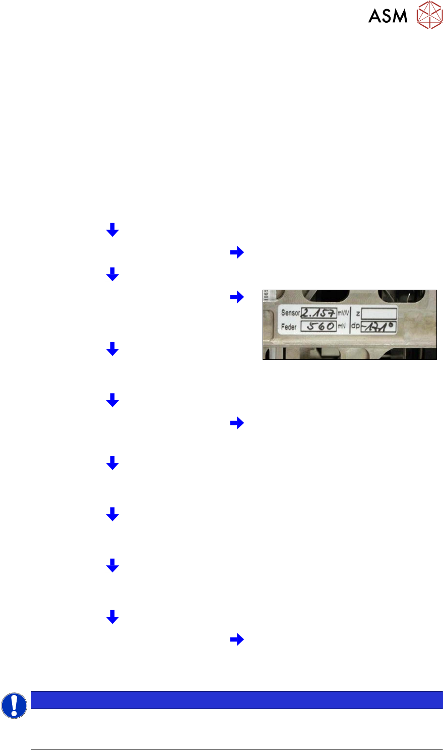
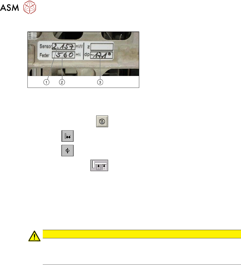
Fig.143: Label with D axis correction value and parameters
for the Twin module
Each Twin module has a label with the cor-
rection values. These correction values must
be entered in SITEST during first operation
or after replacing the Twin module:
1. Sensor (parameter for the DMS strips)
2. Spring (spring pre-tension)
3. dP (zero point correction D axis)
Parameter power sensor and spring pre-tension
► Start the SITEST program .
► Select the button.
► Select the button.
► Select the Twin module.
► Enable the checkbox Z axis.
► Select the Parameter... menu and enter the following values:
– Power sensor calibration value in [mV/V]
This value is always lower than 3.0 [mV/V]
– Spring pre-tension in [mN]
This value is between 300 and 700 [mN]
If these values are not entered in SITEST as specified on the Twin module, this will result in inac-
curate calculation of the placement force (1 to 15N).
CAUTION
Setting screw, spring pre-tension
Do not adjust the setting screw (fine thread) for the spring pre-tension!
It is currently not possible to measure the spring pre-tension at the customer site, meaning
that the placement head needs to be exchanged.
6 Parameter and Calibrations
6.2 Parameters and calibrations SW6xx.x
Service Manual SIPLACE TwinStar (Twin, Twin HF, Twin VHF) 07/2020 83
Zero point correction (ZPC) D axis
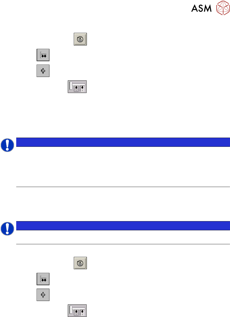
► Start the SITEST program .
► Select the button.
► Select the button.
► Select the Twin module.
► Select the D axis checkbox.
► Select Positions....
► Disable the checkbox Digits.
► Specify the relevant ZPC value in 1/100degrees in line 2 ZPC from the Label and select Ac-
cept.
NOTICE
The D axis value applies for Twin modules1 and2, if the NPC is entered in line 2 at Posi-
tions. The station automatically calculates the ZPC for Twin module 1 (ZPC Twin
module 2 + 180° = ZPC for Twin module 1) :
► Example for the value shown above:
-17100 (module2) or
900 (module1)
► Perform a reference run for the D axis.
► Do not forget to perform D axis calibration afterwards.
Zero point correction (ZPC) Z axis
NOTICE
Enter the zero point correction standard values for the Z axis only if the reference run can-
not be performed.
Requirement: Make sure that the 517 nozzle is on the TwinHead.
► Start the SITEST program .
► Select the button.
► Select the button.
► Select the Twin module.
► Enable the Z axis.
► Select Positions... and enter the following values:
(disable "display in digits")
– Max. travel range: 57500 µm
– Min. travel range: -2000 µm
– Zero point correction: 0 µm
► Perform a reference run for the Z axis.