00197469-02_SM_Twin_Kunde_EN.pdf - 第89页
6 Parameter and Calibrations 6.2 Parameters and calibrations SW6xx.x Service Manual SIPLACE TwinStar (Twin, Twin HF, Twin VHF) 07/2020 89 6.2.6 Calibrating the TwinHead During initial setup or after replacement of a Twin…
6 Parameter and Calibrations
6.2 Parameters and calibrations SW6xx.x
88 Service Manual SIPLACE TwinStar (Twin, Twin HF, Twin VHF) 07/2020
6.2.5.4 Checking the pressure tightness of the vacuum system
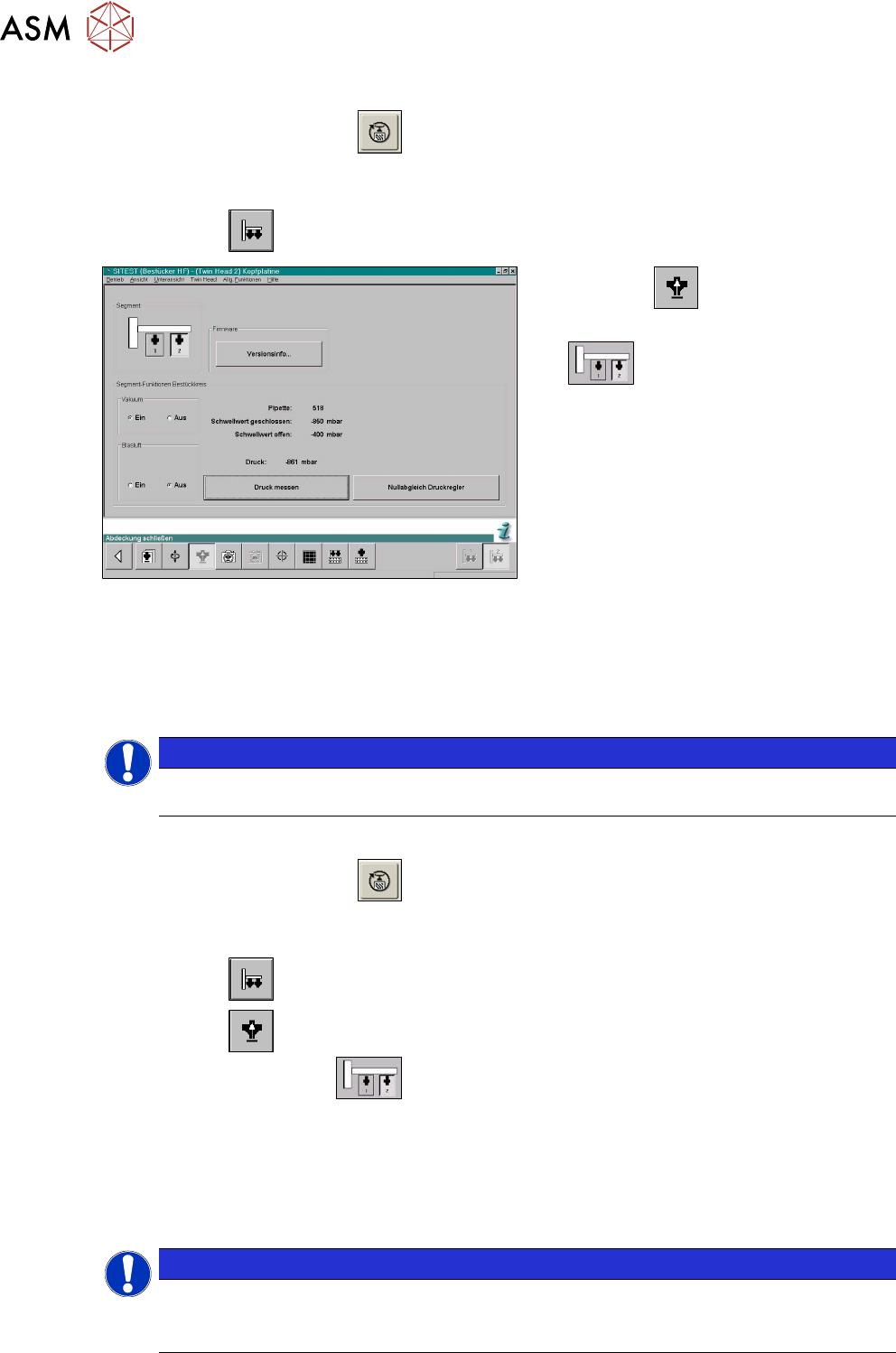
► Start the SITEST program .
► Move the gantry so that you can easily reach the nozzle with one and the keyboard with the
other hand.
► Select the button.
Fig.146: SITEST functions for head board
► Select the button.
► Select the Twin module (segment)
.
► Switch the vacuum on and the air blast off.
► Close the nozzle of the appropriate Twin module (e.g. by sealing it with your finger tip).
► Click on the Measure pressure button.
► The displayed value should correspond to the Closed vacuum.
NOTICE
The Closed vacuum values is determined in the Calibrate TwinHead → Calibrate closed
vacuum menu.
6.2.5.5 Checking the air blast
► Start the SITEST program .
► Move the gantry so that you can easily reach the nozzle with one and the keyboard with the
other hand.
► Select the button.
► Select the button.
► Select the Twin module.
► Switch the air blast On.
► Close the nozzle of the appropriate Twin module (e.g. by sealing it with your finger tip).
► You can edit and modify the value for the air blast pressure or leave the standard value.
► Select Measure pressure.
► The measured value should correspond (approx.) with the given value.
NOTICE
The air blast value can be edited to a value between 0 and 400 mbar, with the SIPLACE
Service password.
► Default setting: 400mbar
6 Parameter and Calibrations
6.2 Parameters and calibrations SW6xx.x
Service Manual SIPLACE TwinStar (Twin, Twin HF, Twin VHF) 07/2020 89
6.2.6 Calibrating the TwinHead
During initial setup or after replacement of a Twin module the TwinHead must be recalibrated. This
menu measures the offset between the TWIN segment and the PCB camera center.
► Put the nozzles 517 by hand on the segments of the Twin modules.
► Make sure that the First garage is empty and that the filling level for the nozzle changer has
been edited accordingly. This is necessary for calibration of the pickup height.
► Enter nozzle "517" as active nozzle on the TwinHead for both nozzles:
► Start the SITEST program .
► Select the button.
► Select the button.
► Select the required Segment (Twin module) from the list.
► Select Edit.
► Mark the nozzle 517 and select the Accept button.
► Enable Selected segment.
► Select Confirm exchange.
► Select All heads and cameras in the main SITEST menu.
► Only select the checkbox TwinHead of the applicable placement area.
► Choose Start.
NOTICE
The following calibration steps are performed automatically:
► MA zero point
► PCB camera
► Calibrating the calibration tool position
► Head height
► TH offset segment 1 and 2
► IC camera (option FC camera)
► Nozzle changer
6.2.6.1 Mechanical adjustment of the Z axis read unit
NOTICE
The incremental encoder on the Z axis must be adjusted to a distance of 0.4mm to the in-
cremental scale. Please adjust the read head parallel to the incremental scale.
After fitting, check the Z axis track signals.

6 Parameter and Calibrations
6.2 Parameters and calibrations SW6xx.x
90 Service Manual SIPLACE TwinStar (Twin, Twin HF, Twin VHF) 07/2020