Infinity High Throughput Conveyor Module.pdf - 第17页
INFINITY +,*+7+ 528*+387&2 19(<2502' 8/( '5,9( 6$1' 6( 16256 Chapter Issue 1 May 03 Technical Reference Manual 15.17 These optos a re fitted wi th a yellow LED al ong with a sensitivity con tro…
INFINITY
+,*+7+528*+387&219(<2502'8/(
'5,9(6$1'6(16256
15.16 Technical Reference Manual Chapter Issue 1 May 03
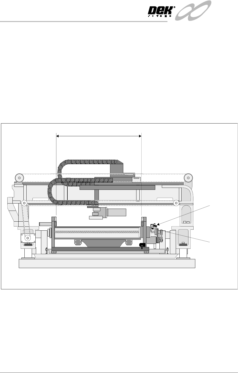
Rail Home Sensor The rail home sensor is a through beam opto type sensor.
The rail home sensor feeds directly to the Multiplexer controller and is used to
set the datum position for the moving rear rail. From this datum position, the
moving rail stepper motor moves the rear rail the amount of steps needed to
obtain the rail width set in the current board file. During machine initialization,
(power-up or upon exiting diagnostics), the rear rail moves to the rear of the
machine until the rail opto vane enters the rail home sensor, the motor is driven
in the opposite direction until the vane clears the home sensor and the motor
stops, the rear rail is now at the home position.
NOTE
The moving rail does not home with Auto Rail Width in Set Prefs set to Disabled,
Homing Sequence of this chapter refers.
Figure 15-12 Rail Home Sensor Location
Board at Left/Right
Sensors
The board at left and board at right sensors are background suppression opto
type sensors.
These two sensors are used to detect a board at the input and output of the print
station rail. As the machine is bi-directional the functions of both sensors are
reversed when the pass through direction is changed.
The input sensor is used to check for the presence of a board when upline
transfer starts. The board is transported to its position and processed after
which it is transferred to the output sensor where it stops unless the downline
conveyor is free to receive it.
Rail Home
Sensor
Rail Home
Opto Flag
(home vane)
508.5 -508.7 mm
Between insideedges of rails
View on Right Hand Side of Machine
INFINITY
+,*+7+528*+387&219(<2502'8/(
'5,9(6$1'6(16256
Chapter Issue 1 May 03 Technical Reference Manual 15.17
These optos are fitted with a yellow LED along with a sensitivity control. There
is a small amount of positional adjustment in the bracket but generally it is not
necessary to reset it.
NOTE
For sensor sensitivity adjustment refer to Adjustment and Settings section of
this chapter.
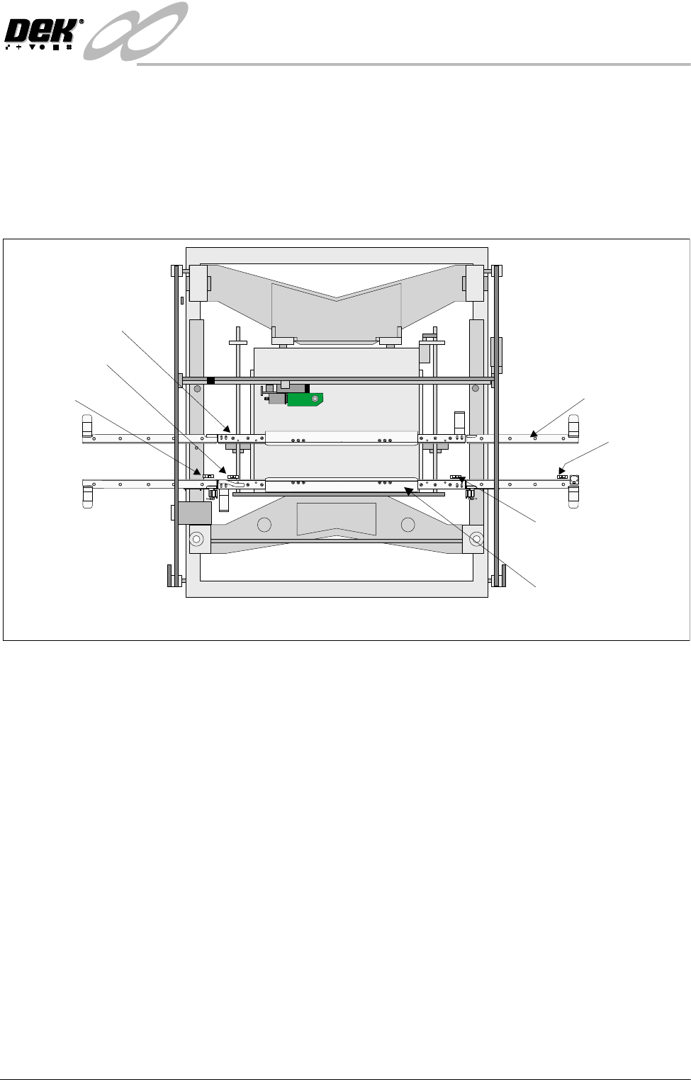
Figure 15-13 Board at Left/Right Opto Sensor Locations
Auxiliary Rail
Sensors
The auxiliary rail sensors are diffuse opto type sensors.
There are two sensors, one on each of the auxiliary conveyors. As the machine
is bi-directional the position of each sensor is reversed when the pass thru
direction is changed.
Each sensor is used to detect a board on the conveyor. The belt motors stop
when a board is detected unless, the downline machine, (which can either be
the print station or an external machine, depending on the conveyor and the
pass thru direction) is free to receive it.
Board at Right Sensor
Board at Left Sensor
Front Print Station Rail
Plan View on Machine - Printhead Removed
PULNIX
TM-6EX
K
E
Y
E
N
C
E
P
Z
-
4
2
L
K
E
Y
E
N
C
E
P
Z
-
4
2
L
K
E
Y
E
N
C
E
P
Z
-
4
2
L
K
E
Y
E
N
C
E
P
Z
-
4
2
L
K
E
Y
E
N
C
E
P
Z
-
4
2
L
K
E
Y
E
N
C
E
P
Z
-
4
2
L
WARNING SHARP EDGE
PATENTNo 5157438
WARNING SHARP EDGE
PATENTNo 5157438
K
E
Y
E
N
C
E
P
Z
-
4
2
L
Auxiliary Rail (4 Positions)
Rear Print Sation Rail
Auxiliary Rail
Sensor
Auxiliary Rail
Sensor
INFINITY
+,*+7+528*+387&219(<2502'8/(
6(48(1&(6
15.18 Technical Reference Manual Chapter Issue 1 May 03
SEQUENCES
Homing Sequence The print station rail is homed during machine initialization only, (during power-
up or upon exiting diagnostics).
NOTE
The moving rail does not home during initialization, with Auto Rail Width in Set
Prefs set to Disabled, but can still be moved in diagnostics.
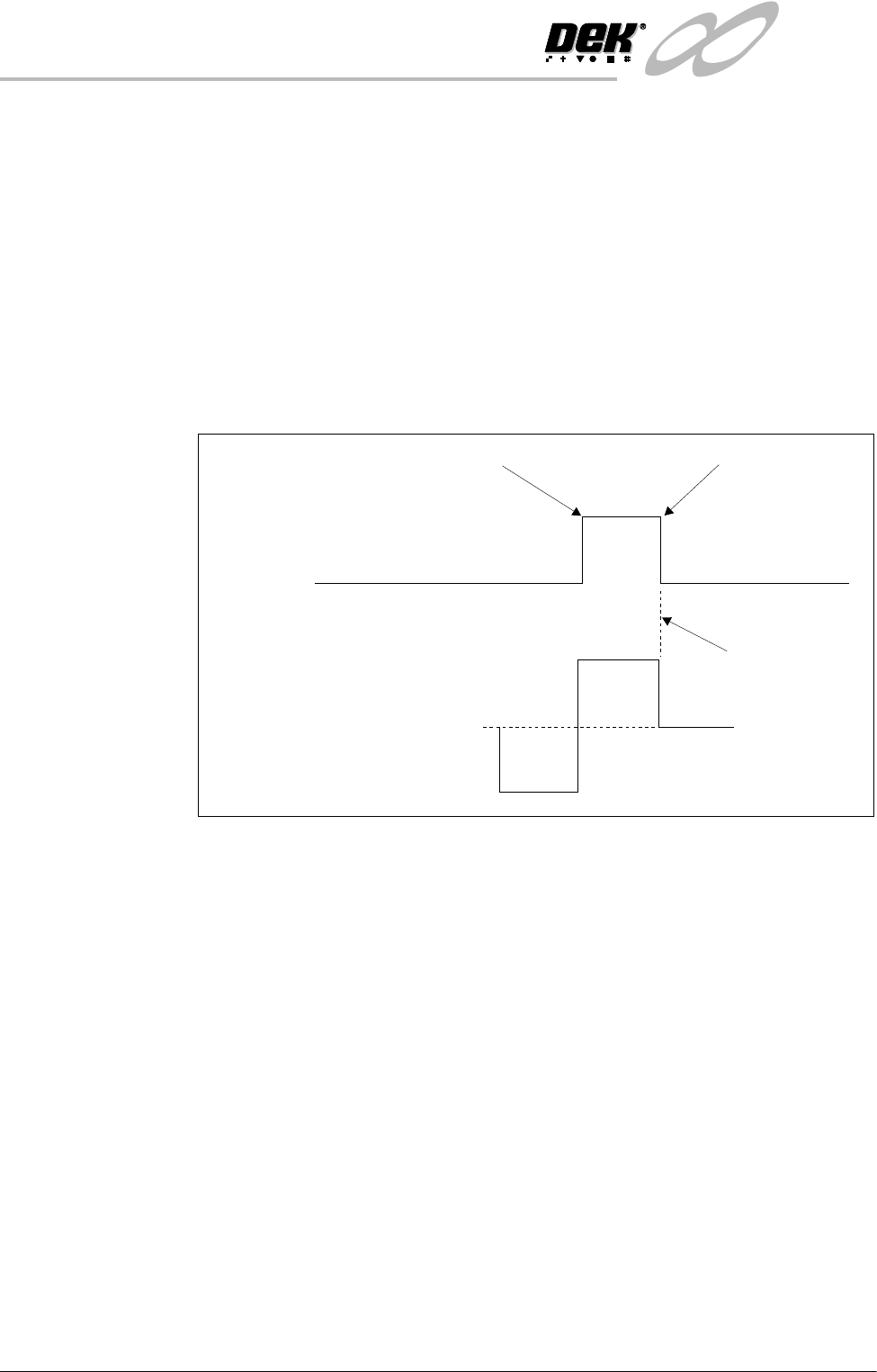
When the home command is received the rear print station rail is driven (in the
reverse direction) to the rear of the machine until the home vane, attached to it,
is detected by the rail home sensor. Upon detection (sensor ON) the motor is
driven in the opposite direction until the vane clears the home sensor and the
motor stops (sensor OFF).
Figure 15-14 Rail Timing Diagram
Rail Positioning There is a fixed relationship between steps of the stepper drive motor and rail
movement (in mm) due to the gearing ratios and pitch of the driving leadscrews.
Therefore, when a width is selected this is multiplied by the steps/mm factor and
sent to the stepper drive system.
All positions are relative to the home position.
Machine
Sequences
The high throughput conveyor system can operate in four modes, selectable on
the M27 located at the rear of the machine.
• Single Stage Normal
• Single Stage Fast
• Three Stage Normal
• Three Stage Fast
NOTE
1. Large apertures in the product board can cause the sensors to activate/
deactivate. In the event of false triggering, select Normal Mode.
2. In the sequences below, the machine is described as working in left to right
Home Position
Fwd
Stepper
Motor
Home
Sensor
0
Stopped
Rev
Vane leaves sensor
Vane enters sensor