Infinity High Throughput Conveyor Module.pdf - 第19页
INFINITY +,*+7+ 528*+387&2 19(<2502' 8/( 6(48 (1&(6 Chapter Issue 1 May 03 Technical Reference Manual 15.19 operati on. Single S tage Normal In singl e stage nor mal mode the aux iliary rails and t he …
INFINITY
+,*+7+528*+387&219(<2502'8/(
6(48(1&(6
15.18 Technical Reference Manual Chapter Issue 1 May 03
SEQUENCES
Homing Sequence The print station rail is homed during machine initialization only, (during power-
up or upon exiting diagnostics).
NOTE
The moving rail does not home during initialization, with Auto Rail Width in Set
Prefs set to Disabled, but can still be moved in diagnostics.
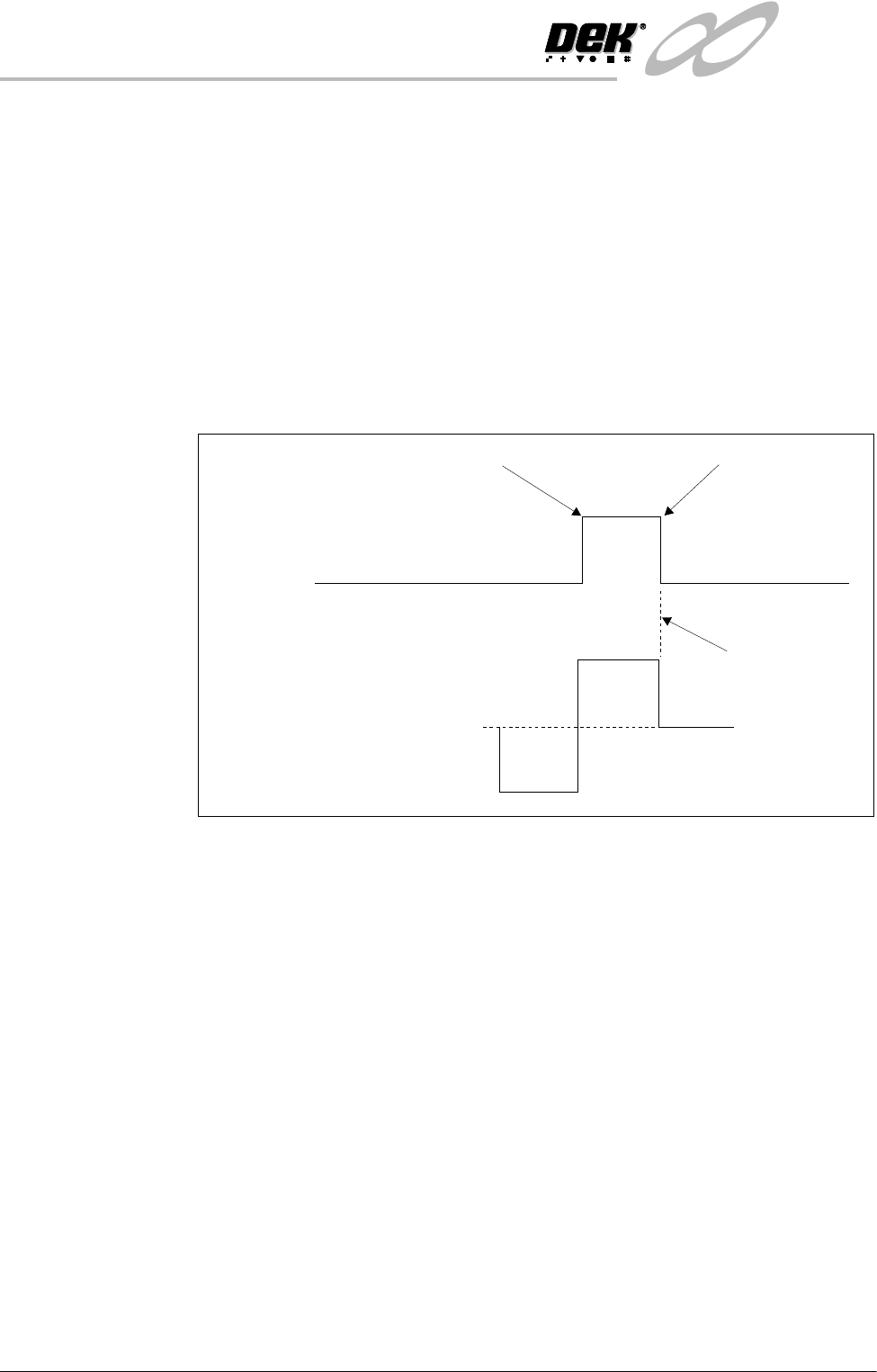
When the home command is received the rear print station rail is driven (in the
reverse direction) to the rear of the machine until the home vane, attached to it,
is detected by the rail home sensor. Upon detection (sensor ON) the motor is
driven in the opposite direction until the vane clears the home sensor and the
motor stops (sensor OFF).
Figure 15-14 Rail Timing Diagram
Rail Positioning There is a fixed relationship between steps of the stepper drive motor and rail
movement (in mm) due to the gearing ratios and pitch of the driving leadscrews.
Therefore, when a width is selected this is multiplied by the steps/mm factor and
sent to the stepper drive system.
All positions are relative to the home position.
Machine
Sequences
The high throughput conveyor system can operate in four modes, selectable on
the M27 located at the rear of the machine.
• Single Stage Normal
• Single Stage Fast
• Three Stage Normal
• Three Stage Fast
NOTE
1. Large apertures in the product board can cause the sensors to activate/
deactivate. In the event of false triggering, select Normal Mode.
2. In the sequences below, the machine is described as working in left to right
Home Position
Fwd
Stepper
Motor
Home
Sensor
0
Stopped
Rev
Vane leaves sensor
Vane enters sensor
INFINITY
+,*+7+528*+387&219(<2502'8/(
6(48(1&(6
Chapter Issue 1 May 03 Technical Reference Manual 15.19
operation.
Single Stage Normal In single stage normal mode the auxiliary rails and the print station rail are
configured as one rail. The rail system transports the board from the upline
machine, into the machine, where the board is positioned, clamped and printed.
After printing, the board is transferred to the downline machine. A signal to the
upline machine, to dispense another board, is sent when the leading edge of
the board switches the ‘board present’ sensor on the downline machine. If the
downline machine has a board at the sensor, the conveyor board stop activates
to prevent the board leaving the print station. In single stage normal mode, only
one board can be in the machine at any one time.
Single Stage Fast In single stage fast mode the signal to the upline machine, to dispense another
board, is sent when the trailing edge of the printed board passes the board at
right sensor on the print station. In the event of the downline machine being
busy, the board is stopped at the end of the print station. In single stage fast
mode, two boards can be in the machine at the same time (one entering the
machine on the upline auxiliary conveyor as the printed board is exiting on the
downline auxiliary conveyor).
NOTE
If the downline transfer time is greater than the machine cycle time (displayed
on the machine MMI), single stage normal mode must be selected to prevent
two boards on the downline conveyor at the same time.
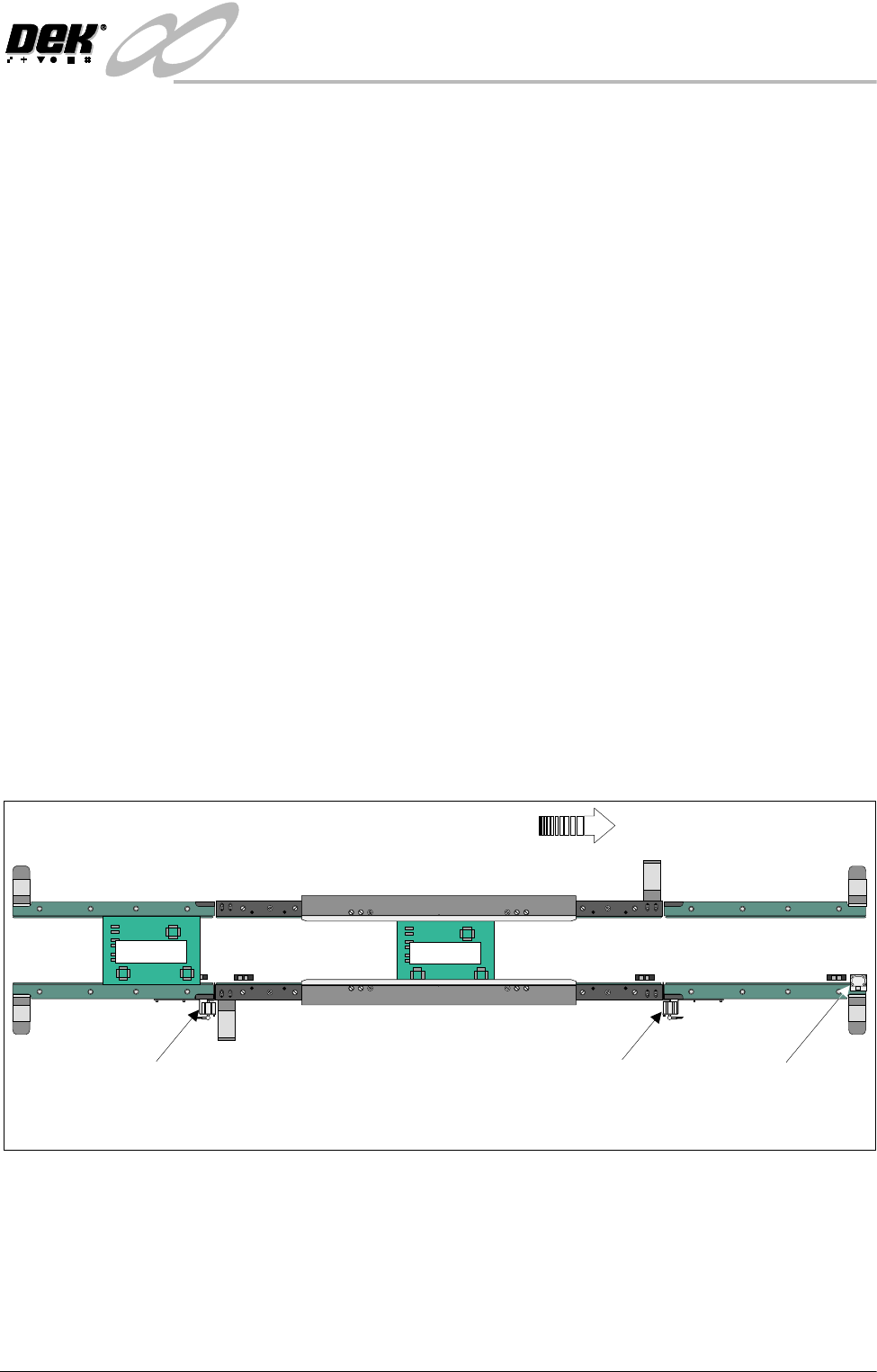
Three Stage Normal In three stage normal mode the upline auxiliary conveyor transports Board 1 to
the print station conveyor where the board is processed. With Board 1 in print
position, Board 2 is dispensed from the upline machine. When Board 2 arrives
at the sensor, at the end of the upline auxiliary conveyor, the transport belts stop.
K
E
Y
E
N
C
E
P
Z
-
4
2
L
Board 1
K
E
Y
E
N
C
E
P
Z
-
4
2
L
K
E
Y
E
N
C
E
P
Z
-4
2
L
K
E
Y
E
N
C
E
P
Z
-
4
2
L
WARNING SHARP EDGE
PATENT No 5157438
WARNING SHARP EDGE
PATENT No 5157438
Print StationConveyor
Board Stop
Downline Conveyor
Board Stop
Upline Conveyor
Board Stop
Plan View of Board Positioning with Downline Machine Delay (Three Stage Mode)
Board Direction from Left to Right
K
E
Y
E
N
C
E
P
Z
-
4
2
L
K
E
Y
E
N
C
E
P
Z
-
4
2
L
Board 2
INFINITY
+,*+7+528*+387&219(<2502'8/(
6(48(1&(6
15.20 Technical Reference Manual Chapter Issue 1 May 03
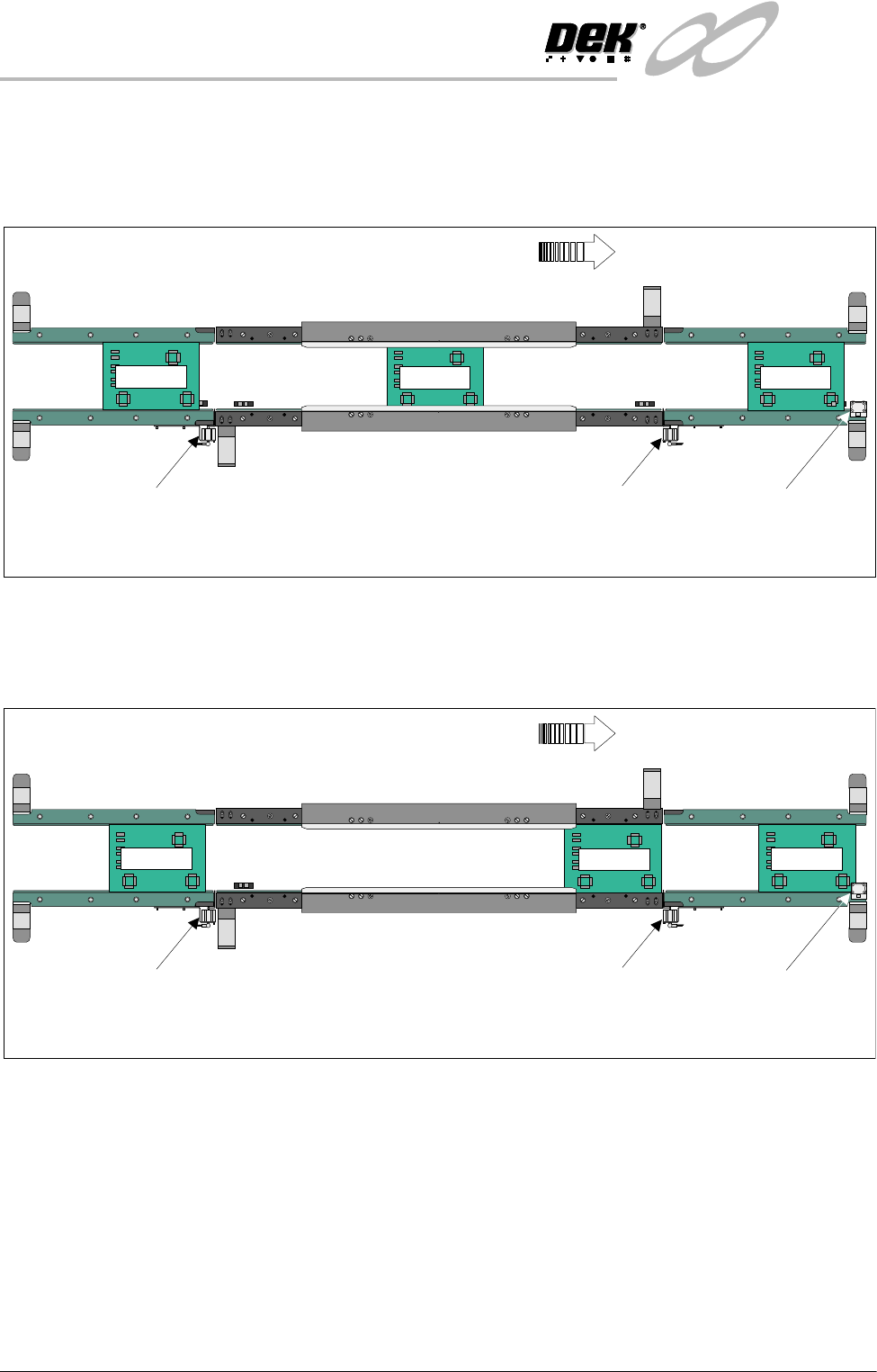
After the print cycle, the Board 1 is then transported to the downline auxiliary
conveyor. When the leading edge of the board activates the sensor, at the end
of the downline auxiliary conveyor, a signal is sent allowing Board 2 to enter the
print station and Board 3 to enter on the upline auxiliary conveyor.
Providing the downline machine is ready, the first board can leave the downline
auxiliary conveyor and the cycle be repeated. If the downline machine is busy,
the second board is printed and transported to the end of the print station
conveyor where it is held by the conveyor board stop.
K
E
Y
E
N
C
E
P
Z
-4
2
L
Board 2
K
E
Y
E
N
C
E
P
Z
-
4
2
L
K
E
Y
E
N
C
E
P
Z
-
4
2
L
K
E
Y
E
N
C
E
P
Z
-
4
2
L
WARNING SHARP EDGE
PATENT No 5157438
WARNING SHARP EDGE
PATENT No 5157438
Print StationConveyor
Board Stop
Downline Conveyor
Board Stop
Upline Conveyor
Board Stop
Plan View of Board Positioning with Downline Machine Delay (Three Stage Mode)
Board Direction from Left to Right
K
E
Y
E
N
C
E
P
Z
-
4
2
L
Board 1
K
E
Y
E
N
C
E
P
Z
-
4
2
L
K
E
Y
E
N
C
E
P
Z
-
4
2
L
Board 3
K
E
Y
E
N
C
E
P
Z
-
4
2
L
K
E
Y
E
N
C
E
P
Z
-
4
2
L
K
E
Y
E
N
C
E
P
Z
-
4
2
L
K
E
Y
E
N
C
E
P
Z
-
4
2
L
WARNING SHARP EDGE
PATENT No 5157438
WARNING SHARP EDGE
PATENT No 5157438
Print Station Conveyor
Board Stop
Downline Conveyor
Board Stop
Upline Conveyor
Board Stop
Plan View of Board Positioning with Downline Machine Delay (Three Stage Mode)
Board Direction from Left to Right
Board 3
Board 2
Board 1