Infinity High Throughput Conveyor Module.pdf - 第22页
INFINITY +,*+7+5 28*+387&21 9(<2502' 8/( $'-8670 (176$1 '6(77,1 *6 15.22 Technical Reference Manual Chapter Issue 1 May 03 ADJUSTMENTS AND SETTINGS Rail Lif ted Sensors 1. From the run menu, se…
INFINITY
+,*+7+528*+387&219(<2502'8/(
6(48(1&(6
Chapter Issue 1 May 03 Technical Reference Manual 15.21
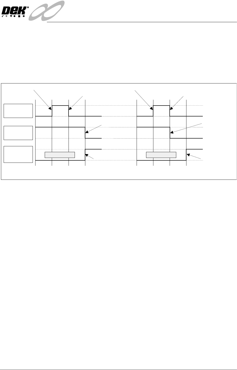
Three Stage Fast In three stage fast mode, the operation is the same as three stage normal mode
with one exception. The second board is transported on to the print station
when the trailing edge of the first board passes the board at right opto situated
at the end of the print station conveyor. This is achieved by the downline
conveyor returning a ‘Busy’ signal back to the centre as soon as it detects that
its ‘Board Available’ input has gone ‘low’, which completes a downline transfer
as far as the print station is concerned.
Figure 15-15 Normal/Fast Mode Timing Chart
Board
Available I/P
Downline
Auxiliary
Sensor I/P
Downline
Available O/P
Belts Running
Normal Mode
Board Available Upline Board Leaves
Upline Machine
Belts Running
Fast Mode
Board Available Upline Board Leaves
Upline Machine
Negative Edge
Frees Upline
Machine
Negative Edge
Frees Upline
Machine
Board Activates
Downline Auxiliary
Sensor
Board Activates
Downline Auxiliary
Sensor
INFINITY
+,*+7+528*+387&219(<2502'8/(
$'-8670(176$1'6(77,1*6
15.22 Technical Reference Manual Chapter Issue 1 May 03
ADJUSTMENTS AND SETTINGS
Rail Lifted Sensors 1. From the run menu, select Maint.
2. Select Diagnost.
3. Select Rising Table. Select Select Module.
4. Select Home Rising Table. Select Run Diagnost, ensure the table moves
to its home position.
5. Select Exit.
6. Select Rail System. Select Select Module.
7. Select Home Rail Width. Select Run Diagnost, ensure the rear rail moves
to its home position.
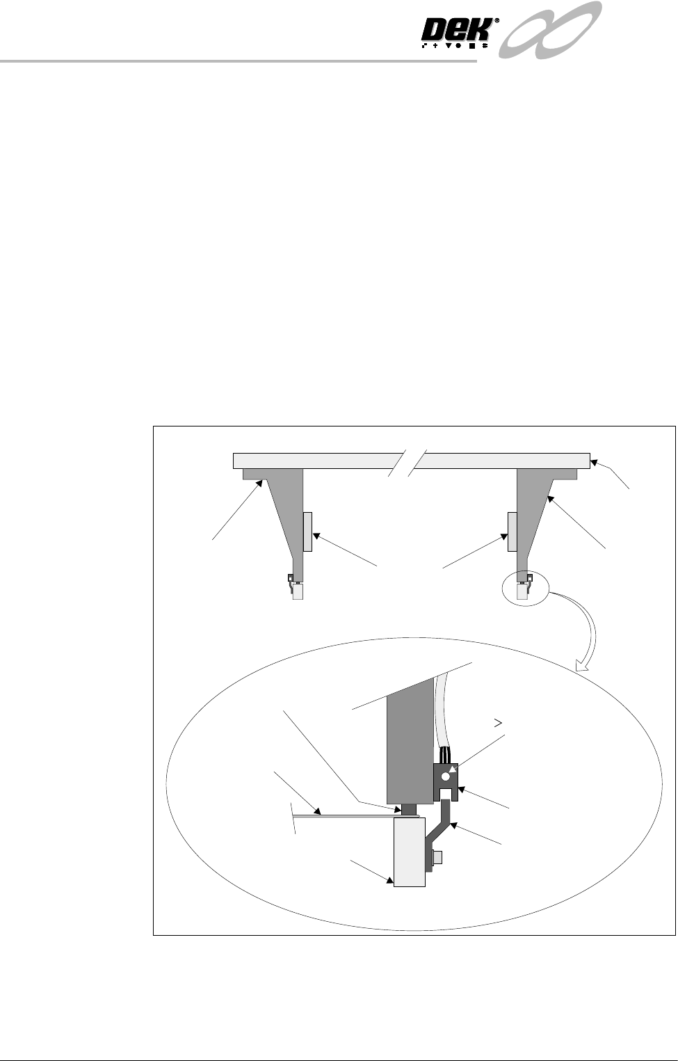
8. Place a 0.5mm feeler gauge between the shock absorber on the rear right
rail transport leg and the rail stop bar (clatter bar). Adjust the vane bracket
using a 2.5mm Allen key, so that the sensor LED is On with a 0.5mm feeler
gauge fitted and Off with a 0.7mm feeler gauge fitted. Lock adjusting
screws.
9. Repeat Step 8 for left hand end of rear rail.
10.Select Drive Rail To Board Width. Select Run Diagnost.
Right Rail
Support Bracket
Main Rear
Rail
Front View of Rail System
Left Rail
Support Bracket
Feeler Gauge
(0.5mm)
Rail Stop Bar
Opto Vane
Bracket
Opto
Shock Absorber
Light Extinguishes
when Sensor lifted
0.5mm
Linear Rail
Enlarged View of Right Rail Opto

INFINITY
+,*+7+528*+387&219(<2502'8/(
$'-8670(176$1'6(77,1*6
Chapter Issue 1 May 03 Technical Reference Manual 15.23
11. Select Adjust, the following window is displayed:
12.Using the Next, Previous, Incr. and Decr. keys, set the Board Width to
50mm.
13.Select Exit.
14.Select Drive Rail To Board Width, the rear rail moves to the new board
width.
15.Repeat Steps 8 and 9 for setting the vane at the 50mm width. Lock adjusting
screws.
16.Select Home Rail Width. Select Run Diagnost, ensure the rear rail moves
to its home position.
17.Repeat Steps 8 and 9 at the home position, adjust vanes if necessary.
18.Select Cycle Rails. Select Run Diagnost, ensure the sensors LED are On
over the full travel of the rail.
Rail Width Home
Sensor
The rail width home sensor is used to find the home position of the moving rail
and is described in detail in the Sequences section (Homing Sequence) of this
chapter.
The sensor is mounted on an adjustable bracket which enables the position
between the front and rear rails to be set at 508.5mm - 508.7mm, (measured
between the inside edges of both rails, when the moving rail is in the home
position).
A fine adjustment can be made to the set rail dimension by slackening the
sensor forward securing screw and turning the home sensor adjustment screw
(Figure Rail Home Setting refers) in accordance with the table below.
NOTE
Rail width home sensor checks are also required if rail parallelism adjustments
are carried out
Rail System Test Parameters
BOARD WIDTH
CYCLE COUNT
250.0
50
mm
Cycles
Home Sensor Screw Adjustment Set Rail Dimension
1 full turn clockwise + 0.5mm
1 full turn anti-clockwise - 0.5mm