Infinity High Throughput Conveyor Module.pdf - 第32页
INFINITY +,*+7+5 28*+387&21 9(<2502' 8/( $'-8670 (176$1 '6(77,1 *6 15.32 Technical Reference Manual Chapter Issue 1 May 03 print st ation and the auxiliary conv eyors (in four posit ions) is 3.…
INFINITY
+,*+7+528*+387&219(<2502'8/(
$'-8670(176$1'6(77,1*6
Chapter Issue 1 May 03 Technical Reference Manual 15.31
rail parallelism to within ±0.2mm.
5. If adjustment is necessary, using an Allen key, slacken the four rail securing
bolts and adjust the rear rail as required. Tighten the bolts, re-check the
parallelism.
6. On completion, carry out Home Position Rail Width check.
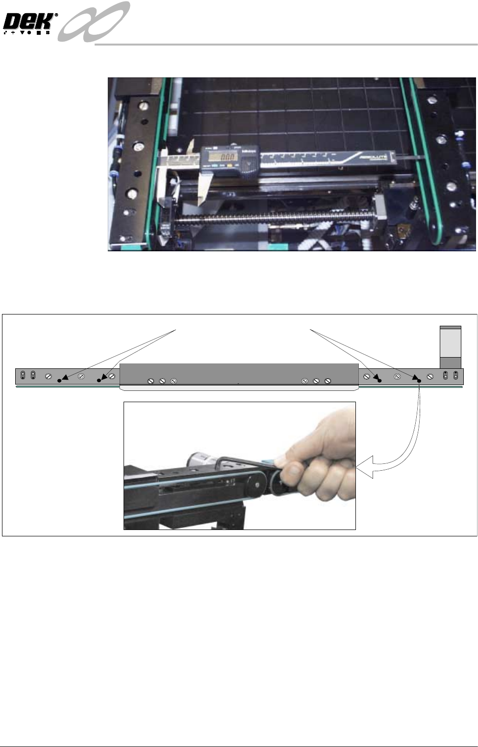
Auxiliary Rail to
Print Station Gap
To check and if required adjust the gaps between the print station rail and the
auxiliary conveyors carry out the following procedure:
NOTE
To carry out this procedure on the front rail, the conveyor board stops must be
removed prior to and refitted on completion of this procedure.
1. Using feeler gauges or a 3mm allen key, ensure that the gap between the
WARNING SHARP EDGE
PATENT No 5157438
Print Station Rail Securing Bolts
INFINITY
+,*+7+528*+387&219(<2502'8/(
$'-8670(176$1'6(77,1*6
15.32 Technical Reference Manual Chapter Issue 1 May 03
print station and the auxiliary conveyors (in four positions) is 3.0 ± 0.5mm.
2. If adjustment is required, loosen the eight auxiliary conveyor rail support
securing bolts (four bolts on each support) that secure the auxiliary conveyor
to the machine lower frame.
3. Adjust the position of the conveyor to obtain the 3.0 ± 0.5mm gap.
4. Re-tighten the securing bolts disturbed in Step 2 and re-check the gap
Board Clamp
Board Transport Rail
Auxiliary Conveyor
Print Station
Plan View on Print Station and Auxiliary Rails
5157438
3.0mm +/- 0.5mm
Rear View of Left Auxiliary Conveyor
Front Auxiliary Conveyor
Rail Support
Rear Auxiliary Conveyor
Rail Support
Rail Support to
Main Frame Bolts
(4 off in 2 positions)
Rear View of Right Auxiliary Conveyor
Front Auxiliary Conveyor
Rail Support
Rear Auxiliary Conveyor
Rail Support
Rail Support to Main Frame
Bolts (4 off in 2 positions)
INFINITY
+,*+7+528*+387&219(<2502'8/(
$'-8670(176$1'6(77,1*6
Chapter Issue 1 May 03 Technical Reference Manual 15.33
measurement.
5. On completion, carry out Front Auxiliary Conveyor Rail Parallelism check.
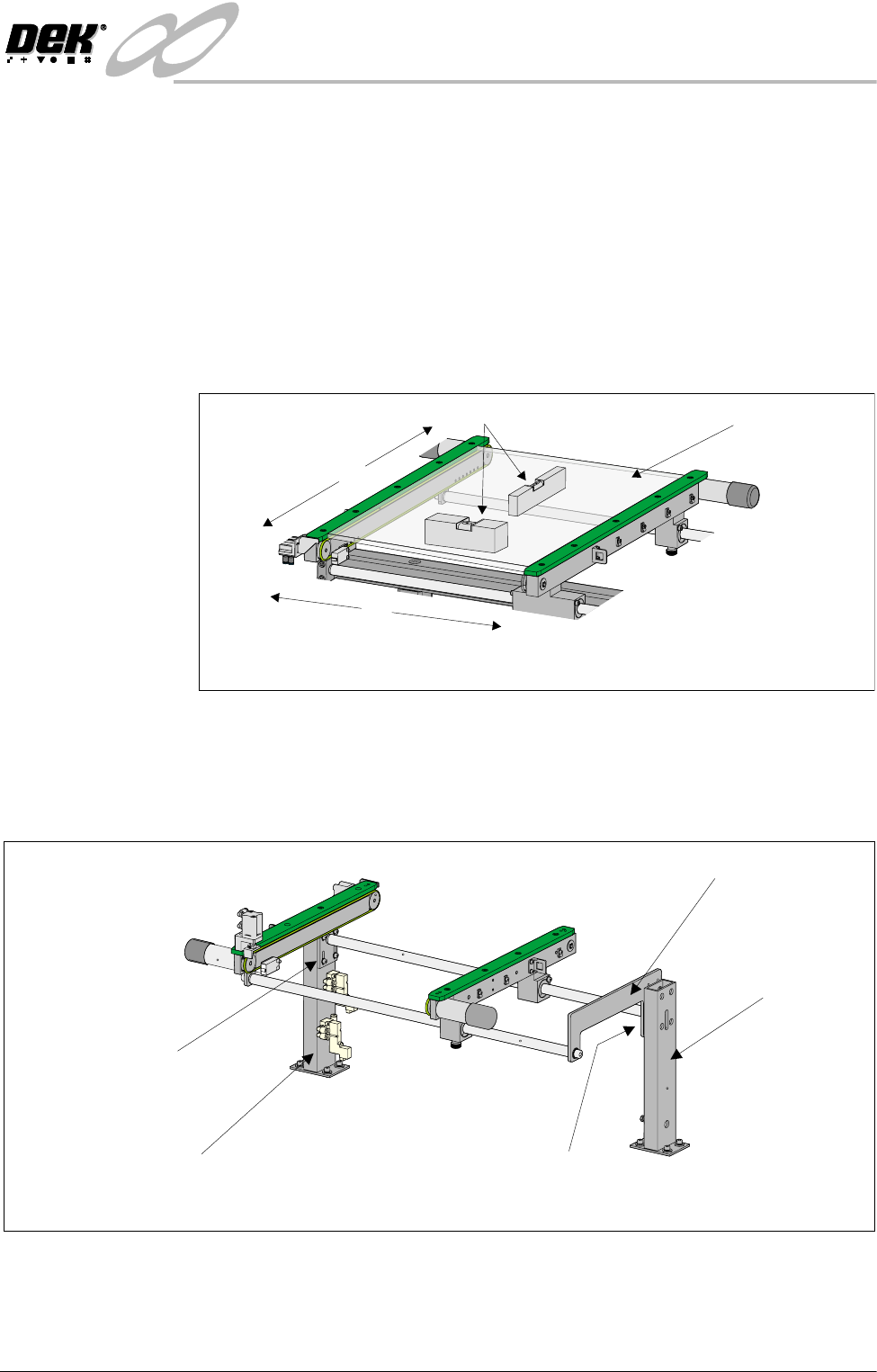
Auxiliary Conveyor
Levelling
To check and if required adjust the levelling of the auxiliary conveyors, carry out
the following procedure:
1. Adjust the auxiliary conveyor rail width to approximately 250mm.
2. Place a Board Clamp Setting Plate Pt No 140403 onto the auxiliary conveyor
transport belts.
3. Place a spirit level on top of the setting plate and check the levelness of the
conveyor in the X and Y planes.
4. If adjustment is required, carry out the following:
a. Loosen the four bolts that secure the auxiliary conveyor shaft guide plate
to the rear rail support and the four bolts that secure the rail bracket to
front rail support.
b. Carefully adjust the height of the auxiliary conveyor rails to achieve
conveyor levelness.
c. Re-tighten the rail bracket and shaft guide plate securing bolts and repeat
the check.
X
Y
Board Clamp
Setting Plate
View on Auxiliary Conveyor
Spirit Level
Rear View of Right Auxiliary Conveyor
Front Auxiliary Conveyor
Rail Support
Rear Auxiliary Conveyor
Rail Support
Shaft Guide Plate
Shaft Guide Plate to Rear
Rail Support Bolts (4 off)
Rail Bracket to Front
Rail Support Bolts
(in 4 positions)