Infinity High Throughput Conveyor Module.pdf - 第37页
INFINITY +,*+7+ 528*+387&2 19(<2502' 8/( $'-8670 (176$1 '6(77,1* 6 Chapter Issue 1 May 03 Technical Reference Manual 15.37 6. Using a spi rit level, pl ace across both s etting plates and check…
INFINITY
+,*+7+528*+387&219(<2502'8/(
$'-8670(176$1'6(77,1*6
15.36 Technical Reference Manual Chapter Issue 1 May 03
8. Loosen the four green wear insert securing bolts.
9. Adjust the insert to allow free movement of the clamp plate and tighten the
bolts.
10.Re-check the rail parallelism and repeat Steps 8 -10 as necessary.
For coarse adjustment carry out the following:
11. Remove the green wear insert securing bolts and remove the insert from the
rail.
12.Loosen the four rail to bearing block securing bolts.
13.Adjust the rail and re-tighten the securing bolts.
14.Refit the green wear insert and re-check the rail parallelism before securing
the insert.
15.If fine adjustments are required, carry out the fine adjustment procedure
above.
16.Tighten the insert securing bolts.
Auxiliary Conveyor
Height Setting
To check and if required adjust the height of the auxiliary conveyor to the print
station rails carry out the following at transport height:
1. In Rail System Diagnostics, select Adjust and alter board width to 250mm.
2. Select Drive Rail to Board Width. The rails are driven to the board width
selected.
3. Adjust the auxiliary conveyor rail width to approximately 250mm.
4. Using a Board Clamp Setting Plate Pt No 140403, place the plate on the
auxiliary conveyor transport belts.
5. Place a second board clamp setting plate onto the transport belts of the print
station. Ensure the plates abut and are fully supported by the transport
belts.
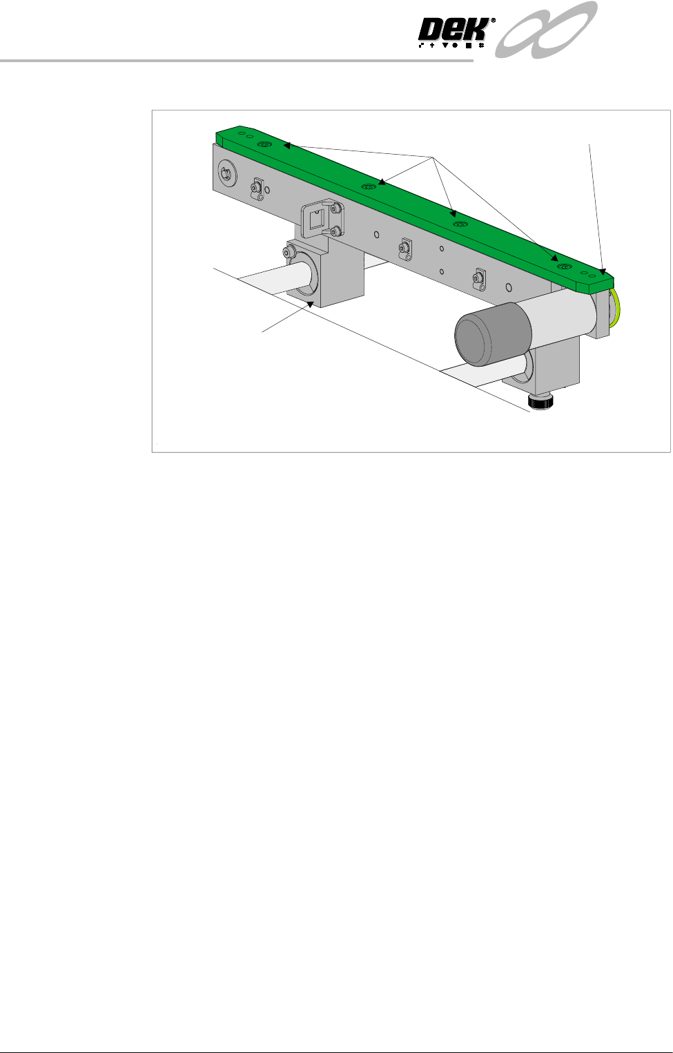
Rear view of Auxiliary Conveyor Rear Rail
Green Wear Insert
Insert Securing Bolts
(in 4 positions)
Bearing Block
(in 2 positions)
INFINITY
+,*+7+528*+387&219(<2502'8/(
$'-8670(176$1'6(77,1*6
Chapter Issue 1 May 03 Technical Reference Manual 15.37
6. Using a spirit level, place across both setting plates and check the plates
are level.
7. If adjustment is required, loosen the four bolts that secure the auxiliary
conveyor guide plate to rear rail support and the four bolts that secure the
rail bracket to front rail support.
8. Carefully adjust the height of the conveyor rails until they match the print
station rails.
9. Re-tighten the securing bolts loosened in Step 7 and repeat the check.
10.If adjustment has occurred, carry out Auxiliary Conveyor Levelling check.
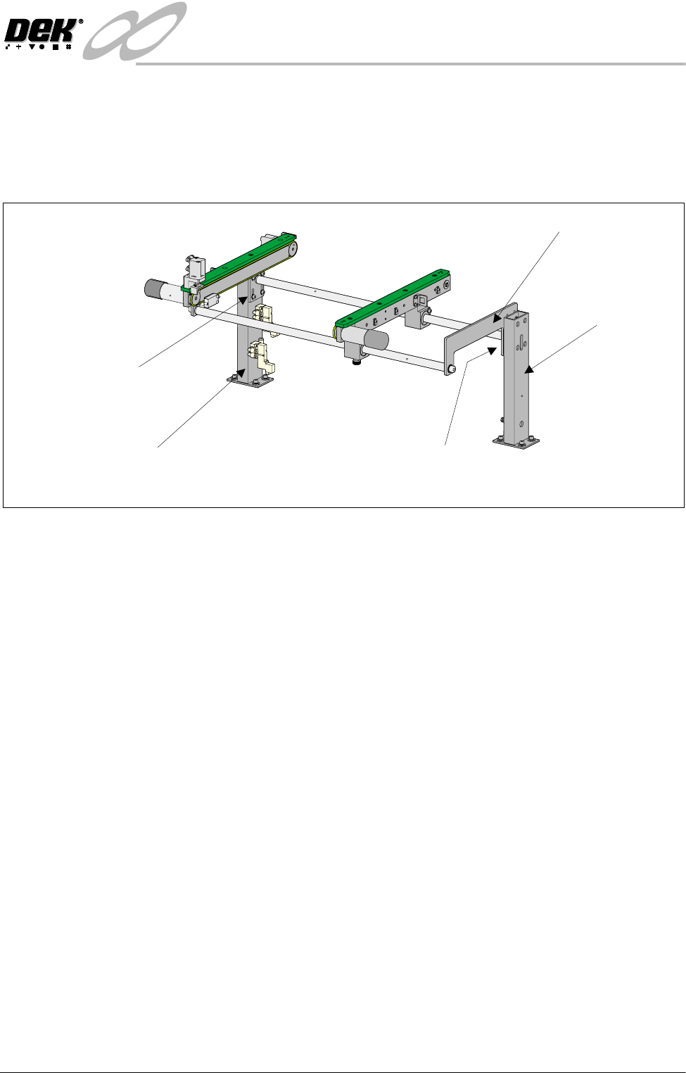
Rear View of Right Auxiliary Conveyor
Front Auxiliary Conveyor
Rail Support
Rear Auxiliary Conveyor
Rail Support
Shaft Guide Plate
Shaft Guide Plate to Rear
Rail Support Bolts (4 off)
Rail Bracket to Front
Rail Support Bolts
(in 4 positions)
INFINITY
+,*+7+528*+387&219(<2502'8/(
$'-8670(176$1'6(77,1*6
15.38 Technical Reference Manual Chapter Issue 1 May 03
Quick Fit Board Clamp Setting
WARNING
BOARD CLAMPS. EXTREME CARE MUST BE EXERCISED WHEN WORKING IN
THE TOOLING AREA OF THE MACHINE TO AVOID INJURY. THE FOILS ON THE
FRONT AND REAR BOARD CLAMPS ARE VERY SHARP.
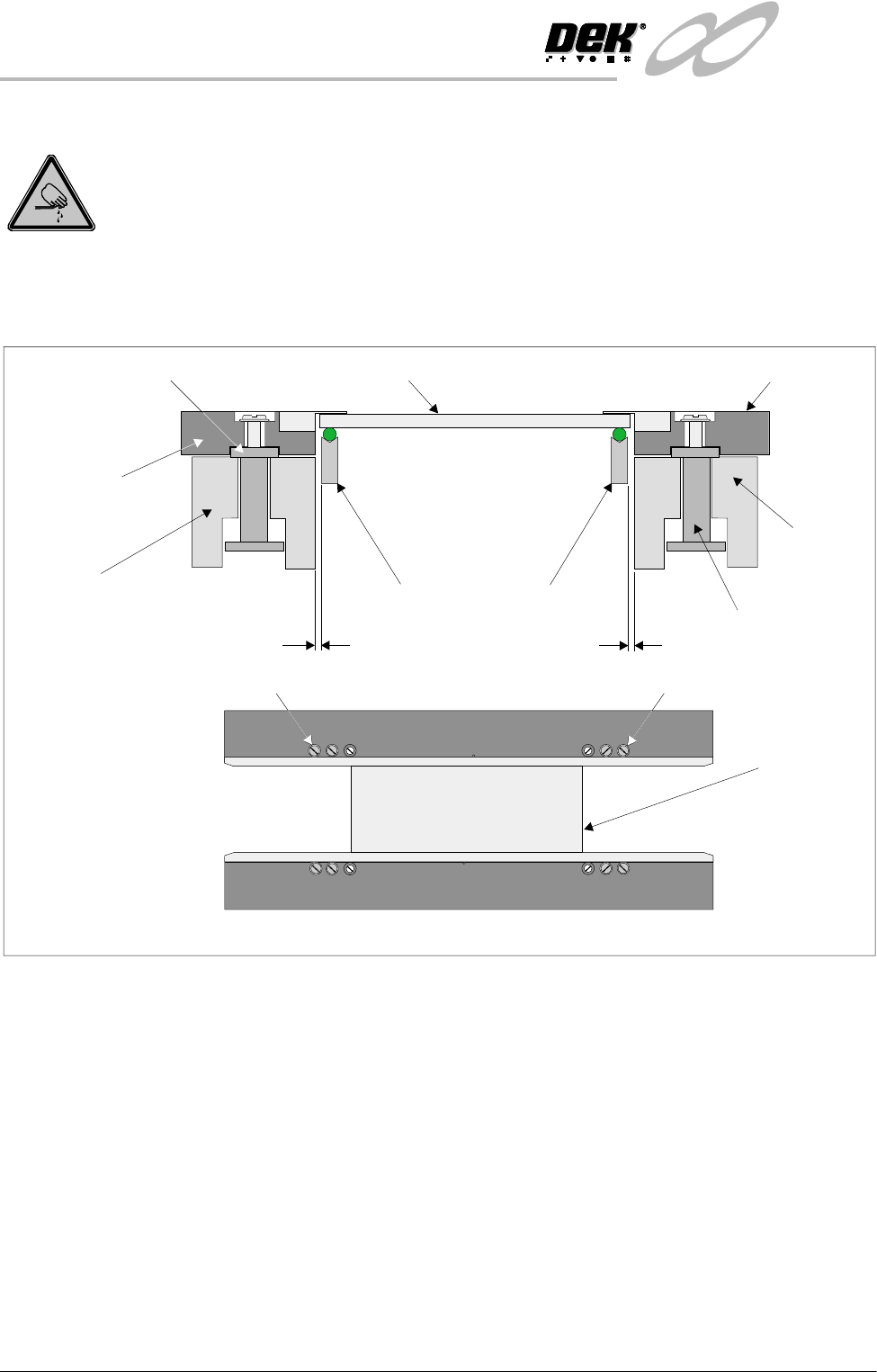
1. Check that a gap between the front board clamp and the transport belt is set
between 0.1mm - 0.15mm. Ensure that the front board clamp is parallel to
the front transport belt.
2. If adjustment is necessary, slacken screw A (2 positions) and adjust.
Tighten screw A (2 positions) on completion.
3. Repeat Steps 1 and 2 for the rear board clamp.
4. Gently move the rear rail in by hand enabling the setting plate (140403) to
be moved along the transport rails until it sits along the entire length of the
board clamp. Gently move the rear rail in by hand until the front and rear
clamps grip the setting plate.
5. Using a 0.05mm feeler gauge check along the whole length of both clamps
for gaps. If the feeler enters any gaps, slacken screws A on the rear board
clamp and adjust. Tighten screws A on completion.
6. If any adjustment is carried out, ensure that gaps set in Steps 1 and 2 are
maintained.
7. Check for correct operation of the board clamps after any adjustment is
made.
WARNING SHARP EDGE
WARNING SHARP EDGE
PATENT No.5157438
PATENT No.5157438
Board Clamp
Setting Plate
A
A
Board Clamp Mechanism
Front Fixed Rail
Transport Belt Guides
0.1mm - 0.15mm
0.1mm - 0.15mm
Board Clamp Mounting Plate
Board Clamp Setting Plate
Front Board Clamp
Rear Board Clamp
Moving Rail
Board Clamp Guide