M6_ServiceManual_e.pdf - 第61页
4 Electrical Section 4-1 4 Electrical Section
3 Mechanical Section
3-30
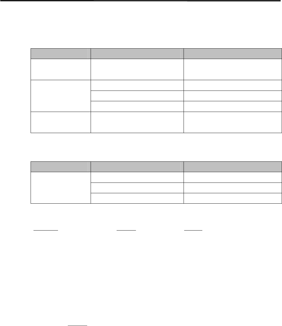
Specified Lubricants
■ M6
PART MANUFACTURER PRODUCT NAME
X/Y Axis
Ball screw
NSK LR3 grease
X/Y/Z/S Axis
THK AFB Grease
Linear guide Showa-Shell Albania Grease No. 2
Ball screw Idemitsu Daphnis Eponex Grease No. 2
Silicone Grease for
Nozzle
Three Bond #1855 Silicone Grease
■ MX-20/MXR-20/MX-ST2
PART MANUFACTURER PRODUCT NAME
THK AFB Grease
Showa-Shell Albania Grease No. 2
All axes
Idemitsu Daphnis Eponex Grease No. 2
■Purchasable Grease from i-pulse
Part Name
Part No. Remark
GREASE,LR3 K48-M3856-00X LR3 Grease
GREASE,AFA LG0-M86A3-00X AFA Grease
GREASE,AFB LG0-M86A4-00X AFB Grease
GUN,GREASE LG0-M86A1-00X Grease Gun and Nozzle set
GREASE,SILICON LG0-M89AB-00X Silicone Grease
NOTE: AFA grease is superior to AFB grease and can be used for all the axes.
NOTE: Order placement for lubricants can be accepted only if the machine is delivered inside Japan. For locations
overseas, please consultant your distributor you purchased the machine.
NOTE: Please specify Part No.
to place an order.

4 Electrical Section
4-1
4
Electrical Section
4 Electrical Section
4-2
Signal I/O
Signal I/O is the abbreviation of signal input/output. The signal input refers to the input signal via the
sensors. The signal output refers to the command transmitted to the actuators.
Signal Output (Control) window serves as controls to move actuators for checking their movements. In
response to their movements, Signal Input (Monitor) window shows On/Off of motors and actuators.
Note: The Signal Input and Signal Out put windows are opened at the same time. You can move actuators using
the Signal Output window while simultaneously checking the signal input status in the Signal Input
window.
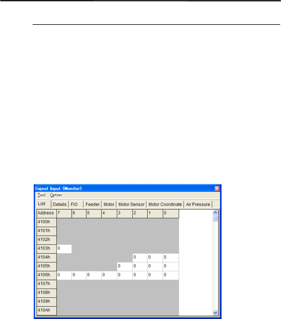
Signal Input Monitor
You can check On/Off of the sensors real-time. “1” indicates on, “0” off. When a sensor of a switch, motor,
and actuator responds, the change of the sensor status is shown real-time. Wire disconnection or sensor
failure can also be detected.
Menu: Manual>Signal I/O>Signal Input (Monitor)
These menus allow you to check each sensor status real-time. You can specify the sampling cycle for the
status check.
■ List tab
■ Changing the Sampling Cycle
Action:
① Select Option>SampingCycle.
② Enter sampling cycle (ms) larger than the minimum of 300, and click <OK> button.
③ Select Tool>StartScan to start checking.
④ Select Tool>EndScan to end.
Note: Use the minimum sampling cycle (300) normally.
Note: The combination of an address and bit number (0-7) represents a signal. The name of each signal is shown
in the Details tab.