M6_ServiceManual_e.pdf - 第74页
4 Electrical Section 4-14 ■ Device 2 Address Bit No. Signal Name Address Bit No. Signal Nam e 0000h 0 Device No. Bit0 0008h 0 Air Pressure: Head A3 Bit 0 1 Device No. Bit1 1 Air Pressure: Head A3 Bit 1 2 Device No. Bit2 …

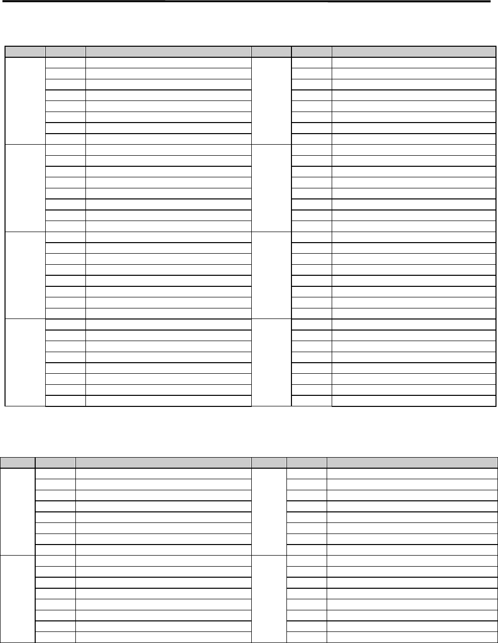
4 Electrical Section
4-13
Signal Input Map
■ DI Monitor
Address Bit No. Signal Name Address Bit No. Signal Name
4103h 0
4105h 0
UPS Under Backup
1
1
UPS Battery Low
2
2
Front Bank Cable Connection
3
3
Rear Bank Cable Connection
4
4
5
5
6
6
7
SERVO ON State
7
4104h 0
24V Voltage monitoring
4106h 0
Reserve DI
1
12V Voltage monitoring
1
Reserve DI
2
5V Voltage monitoring
2
Reserve DI
3
3
Reserve DI
4
4
Reserve DI
5
5
Reserve DI
6
6
Reserve DI
7
7
Reserve DI
4 Electrical Section
4-14
■ Device 2
Address Bit No. Signal Name Address Bit No. Signal Name
0000h 0 Device No. Bit0 0008h 0 Air Pressure: Head A3 Bit 0
1 Device No. Bit1 1 Air Pressure: Head A3 Bit 1
2 Device No. Bit2 2 Air Pressure: Head A3 Bit 2
3 Device Added Information Bit0 3 Air Pressure: Head A3 Bit 3
4 Device Added Information Bit1 4 Air Pressure: Head A3 Bit 4
5 Device Added Information Bit2 5 Air Pressure: Head A3 Bit 5
6 Device Added Information Bit3 6 Air Pressure: Head A3 Bit 6
7 Output Register Value Bit0 7 Air Pressure: Head A3 Bit 7
0001h 0 Output Register Value Bit1 000Ah 0 Air Pressure: Head A4 Bit 0
1 Output Register Value Bit2 1 Air Pressure: Head A4 Bit 1
2 Output Register Value Bit3 2 Air Pressure: Head A4 Bit 2
3 Output Register Value Bit4 3 Air Pressure: Head A4 Bit 3
4 Input Register Value Bit0 4 Air Pressure: Head A4 Bit 4
5 Input Register Value Bit1 5 Air Pressure: Head A4 Bit 5
6 Input Register Value Bit2 6 Air Pressure: Head A4 Bit 6
7 Input Register Value Bit3 7 Air Pressure: Head A4 Bit 7
0004h 0 Air Pressure: Head A1 Bit 0 000Ch 0 Air Pressure: Head A5 Bit 0
1 Air Pressure: Head A1 Bit 1 1 Air Pressure: Head A5 Bit 1
2 Air Pressure: Head A1 Bit 2 2 Air Pressure: Head A5 Bit 2
3 Air Pressure: Head A1 Bit 3 3 Air Pressure: Head A5 Bit 3
4 Air Pressure: Head A1 Bit 4 4 Air Pressure: Head A5 Bit 4
5 Air Pressure: Head A1 Bit 5 5 Air Pressure: Head A5 Bit 5
6 Air Pressure: Head A1 Bit 6 6 Air Pressure: Head A5 Bit 6
7 Air Pressure: Head A1 Bit 7 7 Air Pressure: Head A5 Bit 7
0006h 0 Air Pressure: Head A2 Bit 0 000Eh 0 Air Pressure: Head A6 Bit 0
1 Air Pressure: Head A2 Bit 1 1 Air Pressure: Head A6 Bit 1
2 Air Pressure: Head A2 Bit 2 2 Air Pressure: Head A6 Bit 2
3 Air Pressure: Head A2 Bit 3 3 Air Pressure: Head A6 Bit 3
4 Air Pressure: Head A2 Bit 4 4 Air Pressure: Head A6 Bit 4
5 Air Pressure: Head A2 Bit 5 5 Air Pressure: Head A6 Bit 5
6 Air Pressure: Head A2 Bit 6 6 Air Pressure: Head A6 Bit 6
7 Air Pressure: Head A2 Bit 7 7 Air Pressure: Head A6 Bit 7
■ Device 6
Address Bit No. Signal Name Address Bit No. Signal Name
0000h 0 Device No. Bit0 0002h 0 Start(F)
1 Device No. Bit1 1 Cycle Stop(F)
2 Device No. Bit2 2 Cancel(F)
3 Device Added Information Bit0 3 Alarm Off(F)
4 Device Added Information Bit1 4 Recovery(F)
5 Device Added Information Bit2 5 Servo(F)
6 Device Added Information Bit3 6 Enable(F)
7 Output Register Value Bit0 7 Setup(MXR)
0001h 0 Output Register Value Bit1 0003h 0 Setup(CFB-F)
1 Output Register Value Bit2 1 Go Rear(F)
2 Output Register Value Bit3 2 Auto/Manual Select Switch (F) (1:Auto)
3 Output Register Value Bit4 3 EMG(F)
4 Input Register Value Bit0 4 Front Cover OPEN Detection
5 Input Register Value Bit1 5 EMG Stop External Input
6 Input Register Value Bit2 6 Slowdown External Input
7 Input Register Value Bit3 7

4 Electrical Section
4-15
■ Device 8
Address Bit No. Signal Name Address Bit No. Signal Name
0000h 0 Device No. Bit0 0002h 0 Start(R)
1 Device No. Bit1 1 Cycle Stop(R)
2 Device No. Bit2 2 Cancel(R)
3 Device Added Information Bit0 3 Alarm Off(R)
4 Device Added Information Bit1 4 Recovery(R)
5 Device Added Information Bit2 5 Servo(R)
6 Device Added Information Bit3 6 Enable(R)
7 Output Register Value Bit0 7 Setup(MXR)
0001h 0 Output Register Value Bit1 0003h 0 Setup(CFB-R)
1 Output Register Value Bit2 1 Go Front(R)
2 Output Register Value Bit3 2 Auto/Manual Select Switch (R) (1:Auto)
3 Output Register Value Bit4 3 EMG(R)
4 Input Register Value Bit0 4 Rear Cover OPEN Detection
5 Input Register Value Bit1 5 EMG Stop External Input
6 Input Register Value Bit2 6 Slowdown External Input
7 Input Register Value Bit3 7
■ Device 10
Address Bit No. Signal Name Address Bit No. Signal Name
0000h 0 Device No. Bit0 0005h 0
1 Device No. Bit1 1
2 Device No. Bit2 2
3 Device Added Information Bit0 3
4 Device Added Information Bit1 4 Air Pressure Down (failure)
5 Device Added Information Bit2 5 Ready Input
6 Device Added Information Bit3 6 Board Available Input
7 Output Register Value Bit0 7 AWC Pin Detection
0001h 0 Output Register Value Bit1 0006h 0 CFB(F) Lock
1 Output Register Value Bit2 1 CFB(F) Unlock
2 Output Register Value Bit3 2 CFB(F) Check 1
3 Output Register Value Bit4 3 CFB(F) Check 2
4 Input Register Value Bit0 4 CFB(R) Lock
5 Input Register Value Bit1 5 CFB(R) Unlock
6 Input Register Value Bit2 6 CFB(R) Check 1
7 Input Register Value Bit3 7 CFB(R) Check 2
0002h 0 Board Stopper Up A 0007h 0 ANC A Close
1 Board Stopper Down 1 ANC A Open
2 Main Clamp Up A 2 ANC B Close
3
3
ANC B Open
4 Main Clamp Down 4
5 5
6 6 MXST2 L Position 1
7 Entrance Sensor 7 MXST2 L Position 2
0003h 0 Entrance Shutter Close 0008h 0 Rear Clamp On
1 Buffer Stopper Up 1 Rear Clamp Off
2 Buffer Stopper Down 2 Side Clamp On
3 Main Conveyor Arrival A 3 Side Clamp Off
4 Exit Sensor 4
5 5
6 Entrance Buffer Arrival 6
7 Exit Buffer Arrival 7 Conveyor Width Sensor
0004h 0 000Bh 0 Conveyor1 Alarm
1 1 Conveyor2 Alarm
2 2 Conveyor3 Alarm
3 3
4 X Regenerative Resistor Thermal Alarm 4
5 Y1 Regenerative Resistor Thermal Alarm 5
6 Y2 Regenerative Resistor Thermal Alarm 6
7 7