80S20 circuit.pdf - 第13页
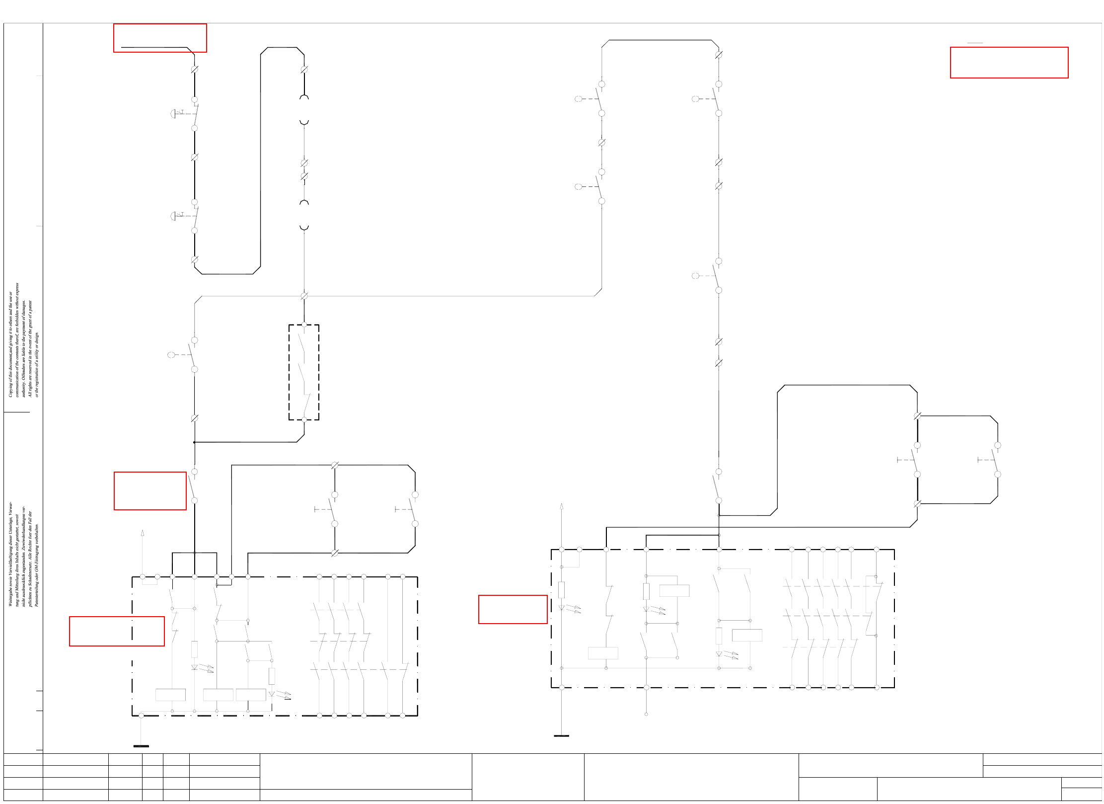
2 SIPLACE 80S-20 Detailed Circuit Diagrams 13 NOTS20-2 EMERG .-STOP circuit - signaling circuit - SIPLACE 80S-20 4 3 4 3 4 3 4 3 2 11 2 blbk blbk (S5 input) (S 5 input) 1 2 (S5 input) Key-operate d switch 00321529- S4 Pu…
2 SIPLACE 80S-20 Detailed Circuit Diagrams 12
2 SIPLACE 80S-20 Detailed Circuit Diagrams
NOTS20-1 EMERG.-STOP circuit, SIPLACE 80S-20
NOTS20-1.DWG
Stromlaufplan/Circuit diagram
SD EA
Hi
10.01.98
SIEMENS
SMD Placement System SIPLACE 80S20
1
2
EMERG.-STOP circuit
SIPLACE 80S20
H2': LED ready
L2
H1': LED release
H1'
3414
24
44
58
K2'
K1'
K1'
K3'
H2'
K2'
L1
K1'
X1 X2 X3
24V AC
K3'
K2'
K3'
K1' K3'
K1'
K2'K1'
X5
K3'
X4 X6
33
13
23 43 57
66
65
H3: LED channel 1
H2+H3 = releasePOWER SUPPLY
H1: LED MAIN
UNIT
L2
X6
H2: LED channel 2
14
54
34
24
44
66
K1'
K2'
H1
L1
K3'
X1 X4
K3'K1'
H3
X211 terminal strip (lefthand side)
Note:
00321432-W1 pk
00321432-W1 gr
00321113-W1 ye
00321434-W1 pk
00321434-W1 gr
00321113-W1 gn
input
push-button
output
push-button
00321528-S2
4
33
4
X211/16
X211/17
00321529-S2
00321113-W1 bl
14
13
00305818-W1 ye
00305818-W1 gn
X211/14
X211/13
22
21
X211/12
Output conveyor
00303617-S1
switch
Protective cover
X211/10
21
22
X211/11
X211/9
21
22
21
22
00305815-W1 ye
00305815-W1 gn
00321573-W1 gn
00321573-W1 ye
00321574-W1 gn
00321574-W1 ye
00303614-S1
Input conveyor
switch
Protective cover
Protective cover
switch
switch
Protective cover
00321417-S1
lefthand side
righthand side
00322070-W1 lbl
00322070-W1 br
00322069-W1 lbl
00322069-W1 br
Component table, righthand side
Component table, lefthand side
00321436-W1 br
00321436-W1 wh
00321433-W1 br
00321433-W1 wh
00321086-xx 24VAC
00321113-W1 wh + br
push-button
push-button
00321529-S1
00321528-S1
X211/4
2
1
X211/3
2
1
X211/2
00321416-S1
X211/5
1a 00322063/X37a
2c 00322063/X37a
X211/6
1a 00322064/X37b
2c 00322064/X37b
00321113-W1 bk
00321434-W1 brgn
00321434-W1 whye
00321113-W1 vio
4
3
X211/15
switch
Key-operated
00321113-W1 rdbl
00321432-W1 ye
00321432-W1 gn
4
3
4
3
00321434-W1 ye
00321434-W1 gn
00321113-W1 grpk
X211/19
X211/18
44
43
00321086-K3
00321528-S2
On
input
00321529-S2
output
On
EMERG.-STOP
EMERG.-STOP
Status Modified Date Name Stand.
Check.
Author
Date
Mat. no.:
CAD file:
Orig./Repl.f/Replaced by
Sh.
Sh.
01.
02.
01.
Doc. status
Product status
Function status
01.08.01
01.08.01
01.08.01 Hi
Hi
Hi
NOTS20-020101LD3
H2
K1
X3
K3'
K1'
24V AC
K2'K2'
K1'
K2'
K2'
X5
K3'
13 53
3323
43
65
conveyor conveyor
OnOn
OPTION: Cover switch, succeeding machine
Connect cable 00305817-W1 to X211/13 gn - X211/14 ye
Warning: If you install the option
remove jumper X211/13 - X211/14.
remove jumper X211/11 - X211/12.
Warning: If you install the option
Connect cable 00305816-W1 to X211/11 gn - X211/12 ye
OPTION: Cover switch, preceding machine
00344265-xx
Push-buttonPush-button
conveyor conveyor
for machine 'ON'
software release signal
Monitoring
for machine 'ON'
software release signal
Monitoring
00321086-K3
54
53
00321086-K1
00321529-S4
X211/8
X211/7
To power supply
Output conveyor
Input conveyor
unit
Safety protection
00321086-K2
Safety protection
00321086-K1
unit
See page 54
See page 52
See page 52
See page 83
See page 52
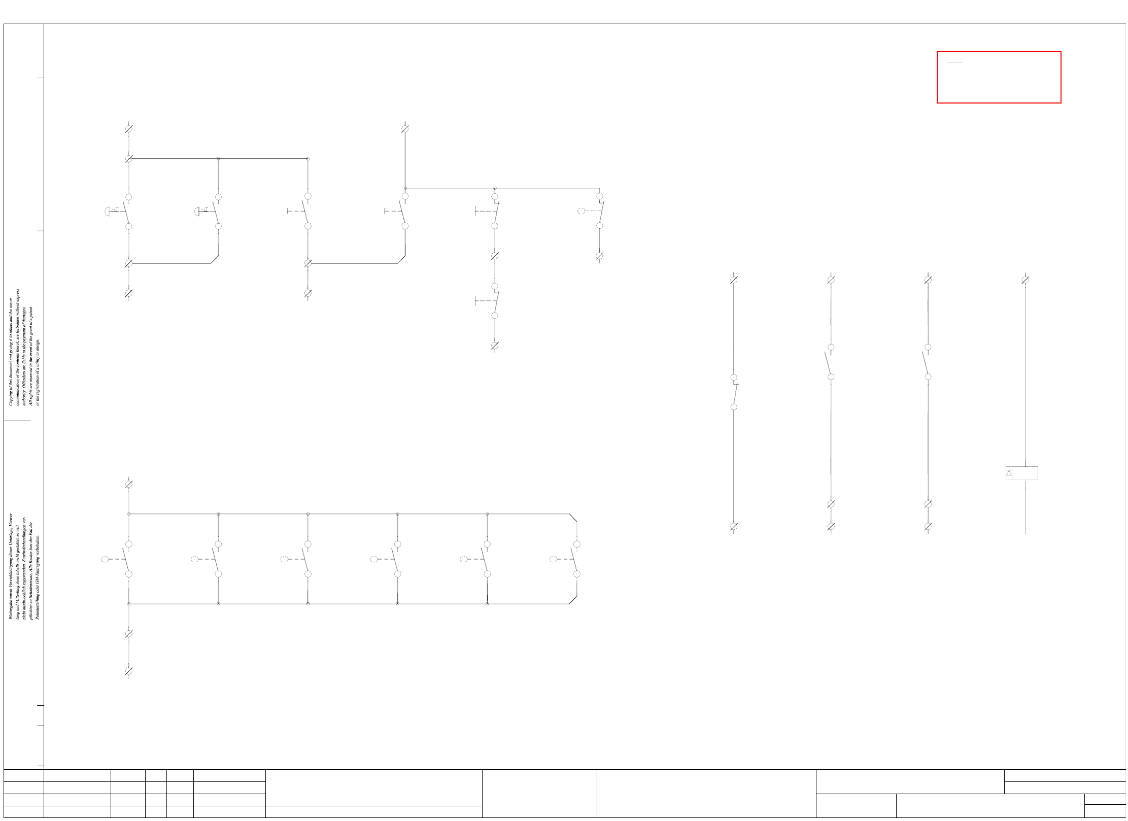
2 SIPLACE 80S-20 Detailed Circuit Diagrams 13
NOTS20-2 EMERG.-STOP circuit - signaling circuit - SIPLACE 80S-20
4
3
4
3
4
3
4
3
2
11
2
blbk blbk
(S5 input) (S5 input)
1
2
(S5 input)
Key-operated
switch
00321529-S4
Push-button
(S5 input)
EMERG.-STOP EMERG.-STOP
Status Modified Date Name
Author
Check.
Stand.
Date
Mat. no.:
Orig./Repl.f/Replaced by
CAD file:
Sh.
Sh.
01.
02.
01.
Doc. status
Product status
Function status
01.08.01
01.08.01
01.08.01 Hi
Hi
Hi
NOTS20-020101LD3
X2XD + (+24VDC)
00321434-W1 rd
X2KD+ (+24V)
X210/3
00321416-S1
00321417-S1 00321614-S1
14
1313
1414
13
00305818-W1 wh
00305818-W1 br
Cover protective
switch
output conveyor
00305817-W1 br
00305817-W1 wh
13
1400303617-S1
13
14
00321086-K3
A2
A1
00321086-K1 00321086-K1
43
44
X211/21
X2KD/8 (S5 input)X2KD/1 (S5 input)
X211/22
58
57
+ 24V+ 24V
X2KB/7 (S5 input)
00321086-K3
22
21
+ 24V
X2KC/8 (S5 output)X212/4X212/4X212/4
K1
00321113-W1 grbr00321113-W1 whgn00321113-W1 whye00321113-W1 whye
00321113-W1 brgn00321113-W1 yebr00321113-W1 whgr
Software release
Monitoring K2
Control On
to GND
Control On
Monitoring K3
Software release
X212 terminal strip (lefthand side)
X211 terminal strip (lefthand side)
X210 terminal strip (lefthand side)
Note:
13
14
Cover protective
lefthand side
switch
Cover protective
00321573-W1 br
switch
righthand side
00321573-W1 wh 00321574-W1 wh
00321574-W1 br
Cover protective
input conveyor
switch
preceding
switch
Cover protective
00305815-W1 br
00305815-W1 wh 00305816-W1 wh
00305816-W1 br
Cover protective
switch
succeeding
NOTS20-2.DWG
Stromlaufplan/Circuit diagram
SD EA
Hi
10.01.98
SIEMENS
SMD Placement System SIPLACE 80S20
2
2
EMERG.-STOP circuit - signaling circuit
SIPLACE 80S20
00344265-xx
Signaling circuit Signaling circuit Signaling circuit Signaling circuit
S5 output
X2KC/M
blbk blbk
monitoring of control ON and software release signal
Signaling circuits
Cover switch signaling circuit
EMERG.-STOP signaling circuits, ON/OFF push-buttons, key-operated switches
blbk
Cover open
X2KD/3 (S5 input)
machine
(Option)
00321421-S1 00321421-S1
(Option)
machine
Push-button Push-button Push-button
blbk
Off button
00321432-W1 vi
00321433-W1 bk
Key-operated switch
00321434-W1 bk00321434-W1 vi00321432-W1 grpk
rd
rdrd
input conveyor
OFF
output conveyor
OFF
X2KD/6X210/5
X2KD/5
00321528-S3
00321529-S3
X210/4
X2KD/4X2KD/2
X210/2
X210/1
X2KD + (+24V)
00321529-S200321528-S200321529-S100321528-S1
On buttonEMERG. STOP
00321433-W1 ye 00321436-W1 ye 00321433-W1 grpk
00321433-W1 rd00321436-W1 gn00321433-W1 gn
ONON
output conveyorinput conveyoroutput conveyor
push-button
input conveyor
push-button
See page 83
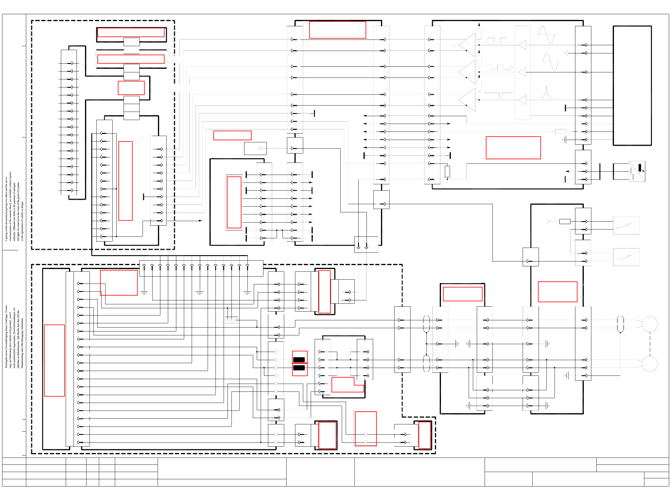
2 SIPLACE 80S-20 Detailed Circuit Diagrams 14
X1-S20 X-axis, gantry 1, SIPLACE 80S-20
X8
Function status
Product status
Doc. status
A18 (va) 00320855
backplane
X-axis
Servo unit
(gantry 1)
GND
01.08.01
01.08.01
X1
proximity switch 1
proximity
End pos.
End position
+V MOT
Brake signal
pkbk
pkgr
A17
00321617-xx
00320927-xx
vi
wh
1+4+7+17+20
screen
X15aa:
1+4+7+17+20
2
3
29
30
33
32
X3aa
(Cable)
Track B
Track B29
30
Track A
Track A
33
32
X15aa
10
12
13
GND
A
A
B
B
N
N
+15V
+5V
U/2
2525
2222
-15V
-15V
+15V
16,3116,31
TT
10
19
GND
+24V
10
19
GND
+24V
3yegr
00321420-xx (W1)
(cable)
bn
wh
bn
wh
bk
00321537-xx
(W1)
00321537-xx
(cable)
Status Modified Date Name Stand.
Check.
Author
Date
Mat. no.:
CAD file:
Orig./Repl.f/Replaced by
Sh.
Sh.
8
9
2
4
5
7
6
3
1
bl
bn
ye
gy
rd
pk
gn
wh
01.
01.
02. 01.08.01 Hi
Hi
Hi
X1-020101LD3
X20:1
X20:2
X20:3
A
B
N
7
+15V
36
-15V
37
TxD1
34
+5V
GND
35
TxD
IREG
20
12
RxD1
INDEX
RxD
9
11
10
TRIG
8
X3sm
V NOM
2
COUNT B
COUNT A
END SIGNAL
I NOM
6
5
4
3
AGND
1
8z
16d
8d
14d
14z
2z
2d
X9ab
3
1
wh
bn
S1 S2
conversion board
X36aa
5
3
4
2
1
(cable)
(aa)
X11aa
23
24
3,5,7,9
2,4,6,8
00321557-xx
524
2,4,6,8
3,5,7,9
M-
M+
1
2
00321189-xx
Conversion board
23
(cable)
X1ab
(ab)
large axis
4
X3ab
T+
T-
M+
M-
1,10,11,12,13,14,15,16,17,18,19,34
00321420-xx (W2)
(cable)
bl
bn
bk
bn
X10aa
2,4,6,8,10,12,14,16,18
3,5,7,9,11,13,15,17,19
X2ab
00321558-xx
(cable)
1,20,341,20,34
X2sz
Machine controller M44 A1 (sa)
A1, 00321732-xx
TDS 120 / 12.5 X
X1
X-axis servo amplifier
screen
1
00324087-xx
Control unit
Cable 00321511-xx
rd
nom. values
X axis
109
Axis rear panel, gantry 1 A27 (sz)
(EN)
8
screen
Servo Enable
3
2
Servo ready
4
control stop
5
I²t
6
Ia monitor
7
14
12
13
10
11
12
13
11
Analog GND
V nom
9
Servo GND
10
std or f/V
12
screen
Force
13
14
Anti-crash board
A15 00322100-xx
00321547-xx
(cable)
X35aa
2
00344265-xx
Terminal strip
X2kf
1
(cable)
00321587-xx
wh
(lefthand side)
gantry 1
Crash signal
00321557-xx
(cable)
13,2813,28
+5V
+5V
11
12
11
12
X10aa
24
X2ab
24
bl3 bl -
X16ac
1
2
(Cable)
00300609-xx
bn
bk bk
bn
+
A1
End pos. prox.
switch B1
+24V
00321190-xx
Gantry
X8ab
3
1
wh
bn
(Cable)
00321577-xx
Limit switch 1
X axis
00321423-xx
proximity switch
B1, B2, Y axis
00321425-xx
Limit switch 2
X axis
00321578-xx
(Cable)
14b
X1va
6z
8b
6d
12d
16z
30+32d,b,z
18+20d,b,z
12z
4d
4z
22+24d,b,z
26+28d,b,z
10d
Sensor
Tachometer -
Servo Enable
2
X3va
1
3
4+15V
EN
T-
T+
3
4
2
X6va
1
X11a
1
2
3
4
yebk
yebk
yebk
yebk
X11e
6
1
X1
X1
1
X34aa
6
pk
bn
-15V
+15V
GND
Dynamic brake
X axis (gantry 1)
00302849-xx, A11
4
18
X12
+/-15V
Power supply
00302841-xx
distributor
Potential
+0/100VDC
StP 009
StP 007
wh
pk
GND
c2,c4,c6,c8
X13
a2,a4,a6,a8
00302850, A16
Ballast cicuit
X1
X1-S20.DWG
Stromlaufplan/Circuit diagram
SD EA
Hi
10.01.98
SIEMENS
SMD Placement System SIPLACE 80S20
1
1
X axis, gantry 1
SIPLACE 80S20
X5
1
3
bn
pk
M+
M-
5
6
T+
T- bn
vi
(W2)
GND
Track B
3
4
2
1
Track A
X-axis incremental shaft encoder
X15ac
6
9
8
7
5
gnwh
bk
rd
bl
wh
bn
ye
pk
gn
Zero pulse
Signal
(Track N)
screen
LED
GND
+5V
LED
00300911-xx
(Cable)
8
9
27
26 Track N
Track N27
26
X3ac
00321554-xx
6
5
X2va
00321538-xx
(Cable)
X11su
X1sz
7
8
5
6
00321036-xx
3
4
1
2
8
9
5
6
2
3
X5su
X1sm
A6 (sm)
SMP bus A32 (su)
Axis board
X22
X7sz
X2sm
X axis,
axis tracks
X1sa
GND
X5va
1
3
T+
T-
X7va
1
2
5
6
M+
M-
X4va
4
1
X7/X1
pkbk
pkbk
wh
18d
26d
24z
16z
10d
8zbrbk
Brake signal
MT
L2
L1
X1/X7
M+
M-
20z
22d
4z
6d
SP6-12
00321214-xx (ac)
head board
Control unit
Power supply
00324087-xx
00344771-xx (A26)
+24V
00321439-xx
(cable)
+5V
+15V
-15V
9
8
7
6
5
+5V
-15V
+15V
+5V
+24V
X18
2
3
4
X12aa
1
+5V
00321190-xx (aa)
Gantry conversion board
switch
Reference point
End pos.
X-axis rel. sign.
Servo unit00321480-xx
See page 64
See page 64
See page 83
See page 111
See page 113
See page 110
See page 111
See page 71
See page 79
See page 71
See page 71
See page 26
See page 71
See page 71
See page 64
See page 68
See page 71
See page 67