80S20 circuit.pdf - 第135页
5 SIPLACE 80S-20 Printed Circuit Boards 135 00347857-020101ND4 922 PCB, vacuum board 2 (Sh. 1 of 2) 00347857-020101ND4 922 PCB, vacuum board 2 (Sh. 2 of 2) A = IDENTI FICATION L ABEL ON THE SIDE OF P1-P 4 B = INS PECTI O…
5 SIPLACE 80S-20 Printed Circuit Boards 134
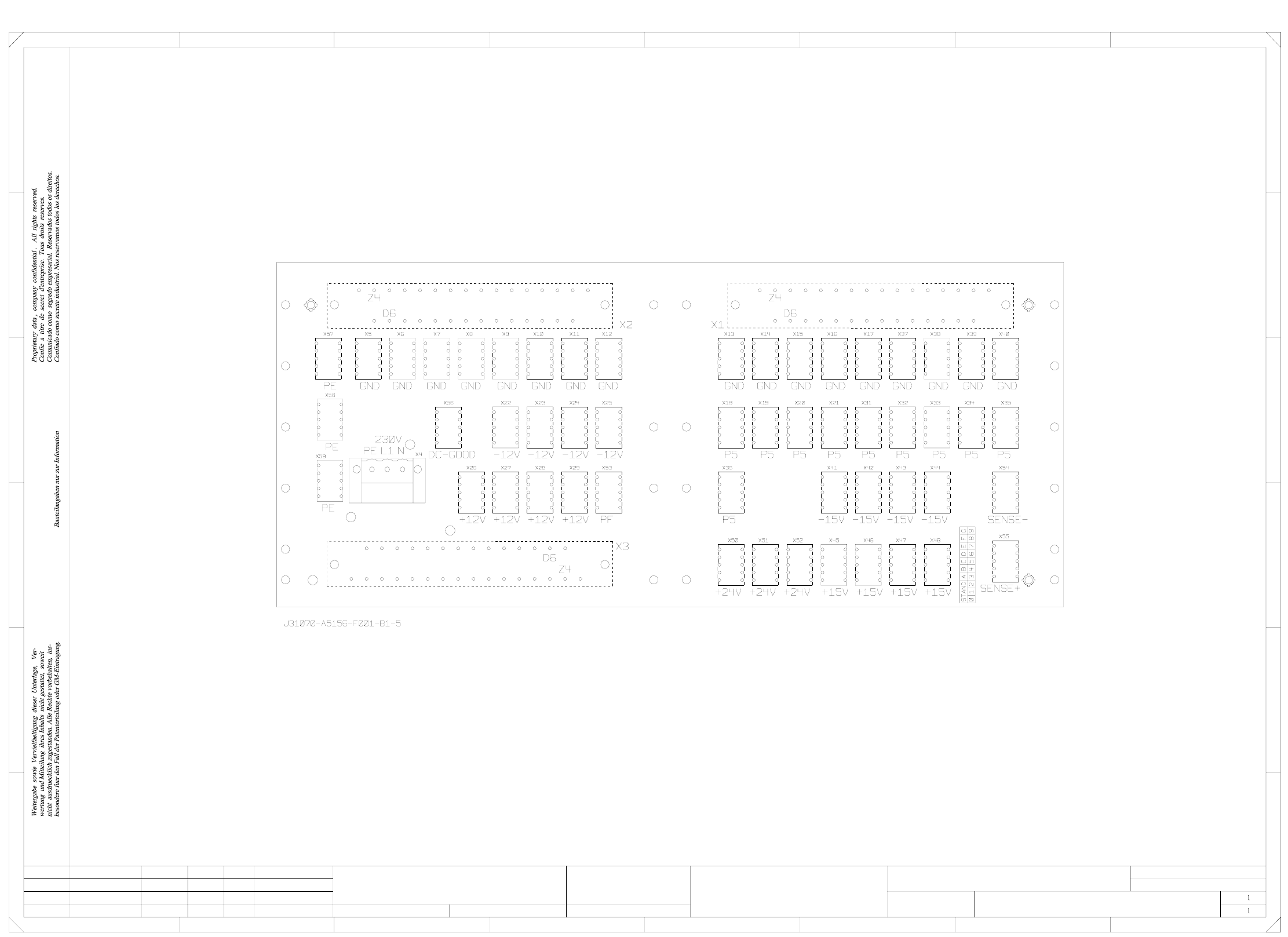
00342582-020101ND3 S23 backplane, component mounting diagram, wired components, side 1
=
Date
Check.
Stand.
Author
Sheet
NameDateModifiedStatus
SIEMENS AG
Sh.
+
C
765432
A
1
E
F F
E
D
B
2
B
8
D
1
A
C
8765
B1 Kg
34
00342582-020101ND3
Component diagram
#
Krieg
08.10.98
08.10.98
Backplane S23
wired component side 1
5156/2
b) space for inspection label
a) space for identification label
Orig. Repl. f. Replaced by
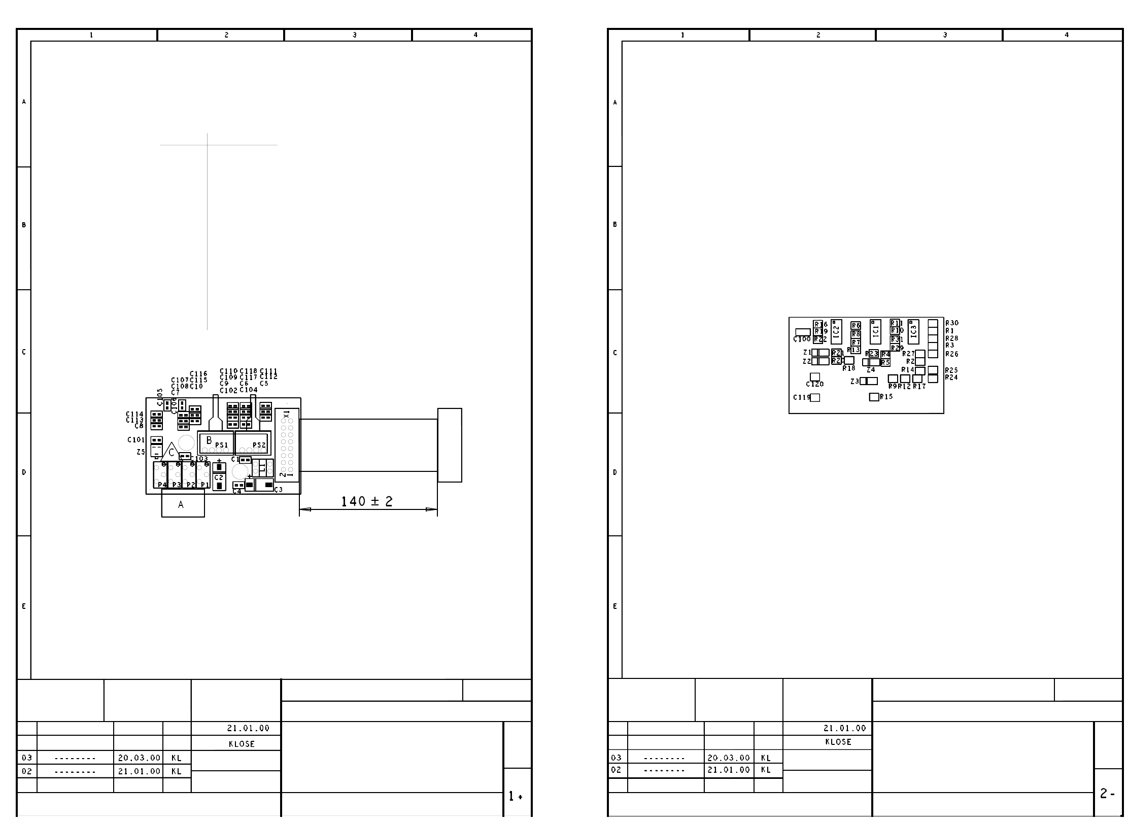
5 SIPLACE 80S-20 Printed Circuit Boards 135
00347857-020101ND4 922 PCB, vacuum board 2 (Sh. 1 of 2)
00347857-020101ND4 922 PCB, vacuum board 2 (Sh. 2 of 2)
A = IDENTIFICATION LABEL ON THE SIDE OF P1-P4
B = INSPECTION LABEL ON PRESSURE SENSORS
C = ESD LABEL
STAT. MODIFIED
DATE
NAME
DATE
NAME
Scale 1 : 1
4-LAYER PC BOARD
COMPONENT LAYOUT, COMPONENT SIDE
BOARD 922
VACUUM BOARD 2
Sheet
4
13
15
14
8
12
11
9
10
6
7
5
X1
3
2
1 + 15 V
- 15 V
N.u.
Holding circuit
GND
AGND
Placement circuit
Placement circuit
AGND
N.u.
Placement circuit
GND
AGND
AGND
AGND
SIEMENS AG
ATD TD MCH 2
00347857-020101ND4
G32918-M0006-B001-*-0017
DATE
NAME
DATE
NAME
Scale 1 : 1
COMPONENT LAYOUT, SOLDER SIDE
4-LAYER PC BOARD
VACUUM BOARD 2
BOARD 922
G32918-M0006-B001-*-0017
00347857-020101ND4
SIEMENS AG
ATD TD MCH 2
STAT. MODIFIED
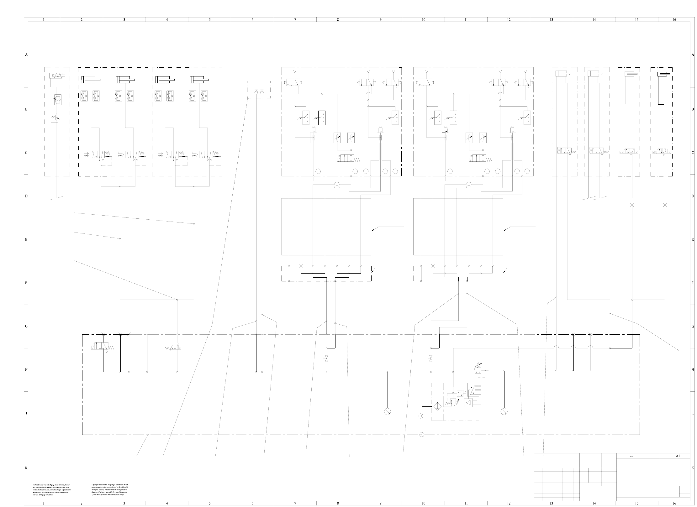
6 SIPLACE 80S-20 Pneumatic Diagrams 136
6 SIPLACE 80S-20 Pneumatic Diagrams
00329027-010202XD1 SIPLACE 80S-20 pneumatic diagram
PU3/2800
PU3/1500
Gantry 2
3
675
43
675
4
PU4/2800
PU4/1900
12
6.
5
24
23
22
20 19 18 17 4
3
11
PU6/1200
PU6/1200
E1
E2
E3
A7
A6
A3
A5
A4
A1
A2
E1
E2
E3
A7
A6
A3
A5
A4
A1
A2
PU6/2400
PU6/2400
EZH-2,5/9-10
1
1
00329027-010202XD1
SIPLACE
---------
01.10.96 Debatin
a
PR
b
B16
5
1
4
3
2
ab
5
1
4
3
2
ab
5
1
4
3
2
ab
5
1
4
3
2
ab
PUN6/1500
PUN6/2600
SIEMENS
AUT 5
Gantry 1
p = 5.2 ± 0.1 bar
p = 2.3 ± 0.2 bar
p = 2.3 ± 0.2 bar
digital
8 Bit
NOMINAL value
internal
external
p = 5.0 - 5.3 bar
5.1 bar
5.1 bar
Cyl.1
Ø 40 ; stroke 30
Cyl.2
Ø 40 ; stroke 30
Cyl.1
Ø 40 ; stroke 30
Cyl.2
Ø 40 ; stroke 30
Valve 1 Valve 2 Valve 1 Valve 2
p max. = 6 bar
for gantry 2
Trailing cable
7-fold hose - 4
7-fold hose - 3
7-fold hose - 7
7-fold hose - 6
7-fold hose - 5
7-fold hose - 2
7-fold hose - 1
7-fold hose - 4
7-fold hose - 3
7-fold hose - 7
7-fold hose - 6
7-fold hose - 5
7-fold hose - 2
7-fold hose - 1
for gantry 1
Trailing cable
Gantry 2
Distributor for
Gantry 1
Distributor for
(lefth. side)
changer
Nozzle
(righth. side)
changer
Nozzle
righth. side
Table
lefth. side
Table
(Option)
centering
Substrate
(Option)
Feeder
Bulk Case
Connecting
(Option)
PCB stopperPCB stopperSpeed-Placer 6-12Speed-Placer 6-12
lefth. side
pneumatically operated
Tape cutter
righth. side
pneumatically operated
Tape cutter
Forced air
Holding circuit
Placement circuit
circuit
Reject
Forced air
Forced air
Holding circuit
Placement circuit
circuit
Reject
Forced air
nozzle dia. 1mm
nozzle dia. 1.5mm
nozzle dia. 1mm
nozzle dia. 1.5mm
Sheet
Sh.
(Model or swage no.)
(Unmachined part no.)
(Material, semifinished products)
Format
(Drawing number)
Scale
Stand.
Check.
Author
Date Name
NameDateModifiedStatus
acc. to ISO 2768 mH
Degree of accuracy
Dimension. variations:
Main no. FS ES US UA S F
S20 pneumatic diagram
US 02 ÄM 10960 03.09.01 Fu.
FS 01 5568/5456 (S20) 01.10.96 Deg.
medium
PS 02 9955 shut-off valve 26.09.00 De.
B15
B14
B13
B12
B11
B10
B7
B9
B6B5
B4
B3
B2
B1
B8
401
B1
401
B1
PU3/2800
PU3/2800