80S20 circuit.pdf - 第137页
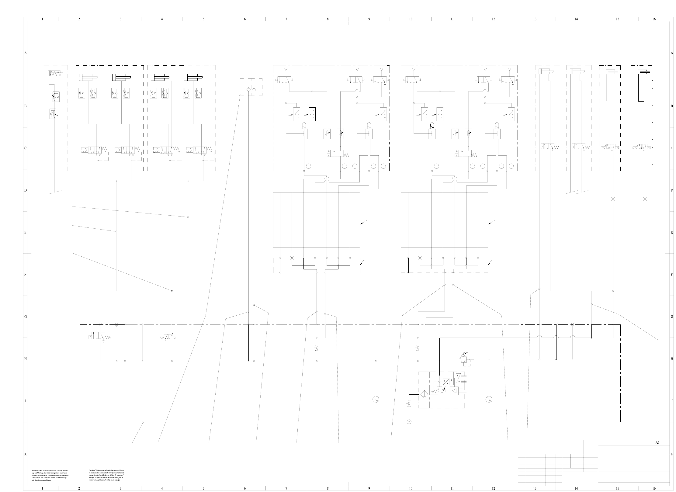
6 SIPLA CE 80S-20 Pneu matic Diagra ms 137 00328647-010201XD3 SIPLACE tape cutte r , pneumatically operated US 01 neu nn.nn.nn ---- 2-5 um chemisch verni ckelt Tiefe:0,3/ 1710xxx X xxxx xxx xx P A3 NN ± N () Valve 1 Valv…
6 SIPLACE 80S-20 Pneumatic Diagrams 136
6 SIPLACE 80S-20 Pneumatic Diagrams
00329027-010202XD1 SIPLACE 80S-20 pneumatic diagram
PU3/2800
PU3/1500
Gantry 2
3
675
43
675
4
PU4/2800
PU4/1900
12
6.
5
24
23
22
20 19 18 17 4
3
11
PU6/1200
PU6/1200
E1
E2
E3
A7
A6
A3
A5
A4
A1
A2
E1
E2
E3
A7
A6
A3
A5
A4
A1
A2
PU6/2400
PU6/2400
EZH-2,5/9-10
1
1
00329027-010202XD1
SIPLACE
---------
01.10.96 Debatin
a
PR
b
B16
5
1
4
3
2
ab
5
1
4
3
2
ab
5
1
4
3
2
ab
5
1
4
3
2
ab
PUN6/1500
PUN6/2600
SIEMENS
AUT 5
Gantry 1
p = 5.2 ± 0.1 bar
p = 2.3 ± 0.2 bar
p = 2.3 ± 0.2 bar
digital
8 Bit
NOMINAL value
internal
external
p = 5.0 - 5.3 bar
5.1 bar
5.1 bar
Cyl.1
Ø 40 ; stroke 30
Cyl.2
Ø 40 ; stroke 30
Cyl.1
Ø 40 ; stroke 30
Cyl.2
Ø 40 ; stroke 30
Valve 1 Valve 2 Valve 1 Valve 2
p max. = 6 bar
for gantry 2
Trailing cable
7-fold hose - 4
7-fold hose - 3
7-fold hose - 7
7-fold hose - 6
7-fold hose - 5
7-fold hose - 2
7-fold hose - 1
7-fold hose - 4
7-fold hose - 3
7-fold hose - 7
7-fold hose - 6
7-fold hose - 5
7-fold hose - 2
7-fold hose - 1
for gantry 1
Trailing cable
Gantry 2
Distributor for
Gantry 1
Distributor for
(lefth. side)
changer
Nozzle
(righth. side)
changer
Nozzle
righth. side
Table
lefth. side
Table
(Option)
centering
Substrate
(Option)
Feeder
Bulk Case
Connecting
(Option)
PCB stopperPCB stopperSpeed-Placer 6-12Speed-Placer 6-12
lefth. side
pneumatically operated
Tape cutter
righth. side
pneumatically operated
Tape cutter
Forced air
Holding circuit
Placement circuit
circuit
Reject
Forced air
Forced air
Holding circuit
Placement circuit
circuit
Reject
Forced air
nozzle dia. 1mm
nozzle dia. 1.5mm
nozzle dia. 1mm
nozzle dia. 1.5mm
Sheet
Sh.
(Model or swage no.)
(Unmachined part no.)
(Material, semifinished products)
Format
(Drawing number)
Scale
Stand.
Check.
Author
Date Name
NameDateModifiedStatus
acc. to ISO 2768 mH
Degree of accuracy
Dimension. variations:
Main no. FS ES US UA S F
S20 pneumatic diagram
US 02 ÄM 10960 03.09.01 Fu.
FS 01 5568/5456 (S20) 01.10.96 Deg.
medium
PS 02 9955 shut-off valve 26.09.00 De.
B15
B14
B13
B12
B11
B10
B7
B9
B6B5
B4
B3
B2
B1
B8
401
B1
401
B1
PU3/2800
PU3/2800
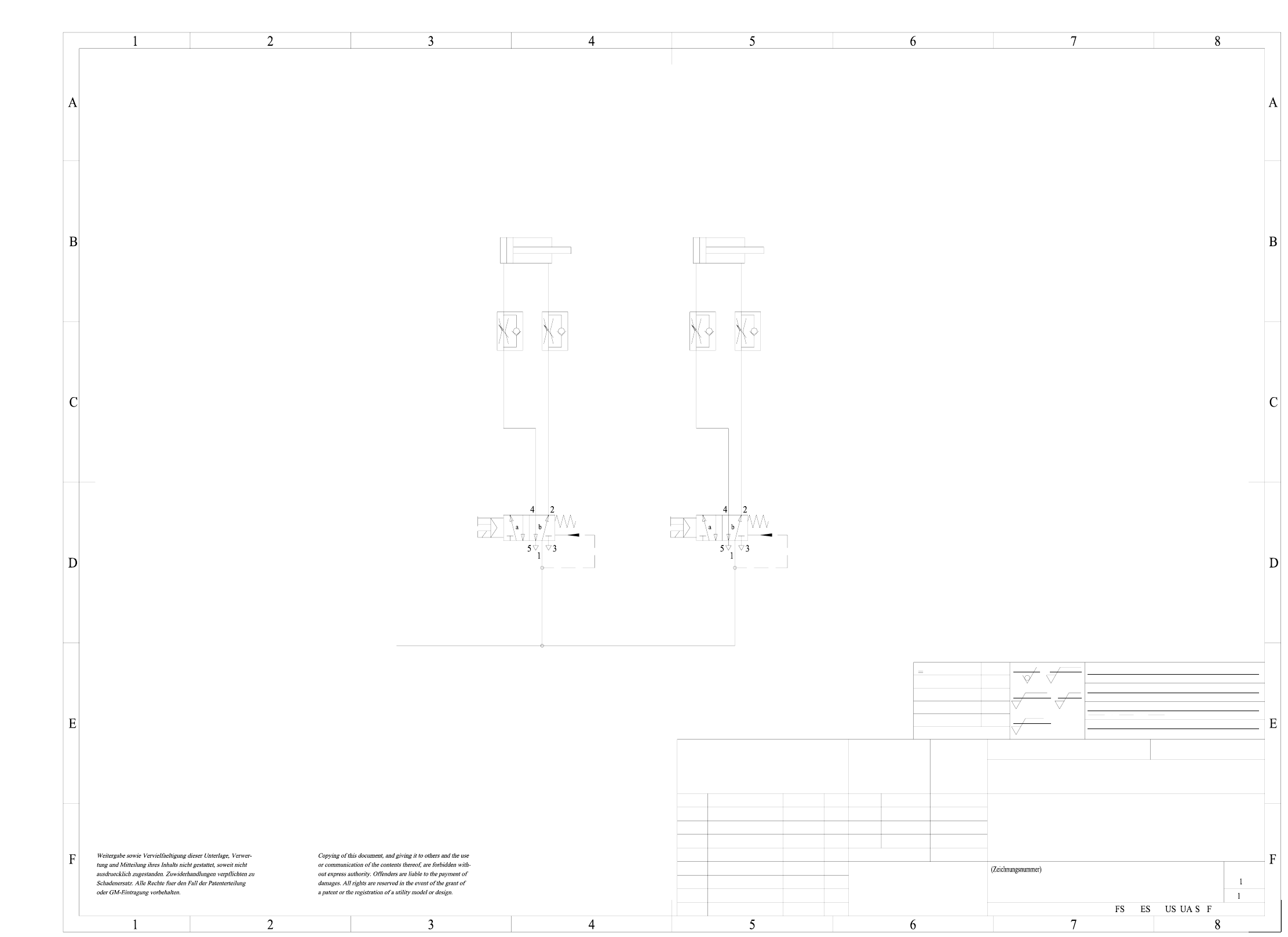
6 SIPLACE 80S-20 Pneumatic Diagrams 137
00328647-010201XD3 SIPLACE tape cutter, pneumatically operated
US 01 neu nn.nn.nn ----
2-5 um chemisch vernickelt
Tiefe:0,3/
1710xxx Xxxxx xxx xx P
A3
NN ± N
()
Valve 1 Valve 2
Compressed air supply
of servicing unit
machine
Cyl.1
Ø 40 ; Stroke 30
Cyl.2
Ø 40 ; Stroke 30
Sheet
Sh.
R 1
z
R 6,3
z
R 25
z
R 100
z
einsatzgehaertet
gehaertet HRc
Oberfl.:
±0,8
±0,5
±0,3
±0,2
±0,1
>400...1000
>120...400
>30...120
>6...30
<6
AUT 5
SIEMENS
00328647-010201XD3
Tape cutter, pneumatically operated
Siplace
14.04.97
Berndl
Zustand Mitteilung Datum Name
Bearb.
Gepr.
Norm
Freimasstoleranzen:
Genauigkeitsgrad
mittel
nach ISO 2768 mH
Datum
Name
Massstab
(Werkstoff,Halbzeug)
(Rohteil-Nr)
(Modell- oder Gesenk-Nr)
Stamm-Nr.
Format
Freimasstoleranzen
Hierzu gehoert
Koordinatenliste:
Zeichnungen2/A
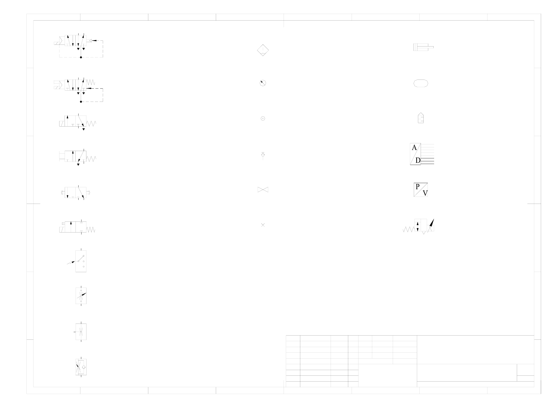
6 SIPLACE 80S-20 Pneumatic Diagrams 138
00329906-010101EX3 Pneumatic symbols
1
5/2-way solenoid valve without manual override
3/2-way valve, manually operated
by push-button
3/2-way valve, manually operated
Electrical switch
with mechanical spring return
Flow control valve, adjustable
Flow control valve
Flow control valve with flow adjustable in one direction
Quick acting coupling uncoupled,
Pressure source
Filter with water separator
Pressure gauge
closed by non-return valve
Shut-off valve
8
Sheet
Sh.
1234 765
F
E
D
C
A
B
F
E
D
C
A
B
1234 8765
SD EA
SIEMENS
FS ES US UA S F
1
00329906-010101EX3
Pneumatic symbols
01.07.2001
Hi
Hi
01.07.01
Name
Status
Date
DS 01
new
Modified
Name
Date
Stand.
Author
Check.
Main no.
(Drawing number)
with pneumatic spring return
with mechanical spring return
5/2-way solenoid valve with manual override
3/2-way solenoid valve without manual override
with mechanical spring return
2/2-way solenoid valve with manual override
with mechanical spring return
Plug Regulator with exhaust
Pressure / voltage converter
Analog / digital converter
Silencer
Air reservoir
Double acting cylinder
with manual draining
53
24
1
1
53
42
A
RP
ab
A2
R3 P1
b
a