80S20 circuit.pdf - 第33页
2 SIPLACE 80S-20 Detailed Circuit Diagrams 33 LP6-S20 PCB conveyor 2, co nveyor motor control 11 10 7 8 13,14 1,2,3,4 12 1,2,3,4 13,14 9 8 7 12 11 10 Port A5.4 Port A5.5 Port A5.6 Port A5.7 I/O boards Port A1.5 Port E1.2…
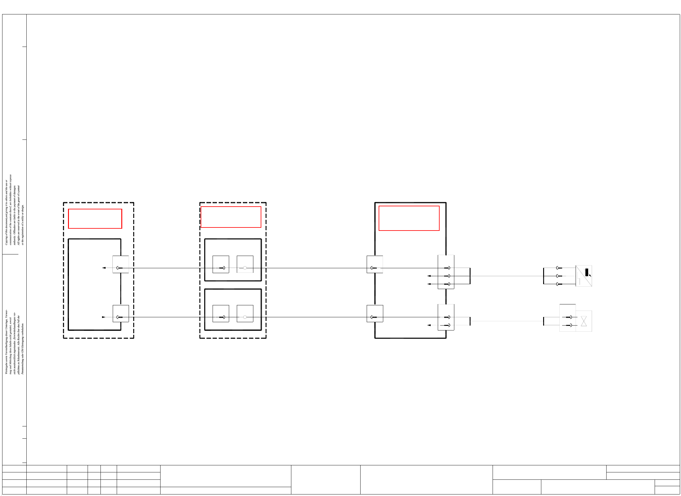
2 SIPLACE 80S-20 Detailed Circuit Diagrams 32
LP5-S20 Ceramic substrate centering
X13
7
X12
7
00326069-xx
(Cable)
00326068-xx
(Cable)
bl
bl
Sensor switch
Valve, ceramic substrate centering 1
Ceramic substrate centering 1
Ceramic substrate
Sensor switch
bk
GND
bn
bl -
+
bk A1
(Cable)
00326029-xx
B1
2
1
X40
bn
wh
00326028-xx
Valve
centering 1
centering 1
Ceramic substrate
Sheet
Sh.
Status Modified Date Name Stand.
Check.
Date
Author
CAD file:
Mat. no.:
Orig./Repl.f/Replaced by
02.
01.
01. 18.03.02
Doc. status
Hi
18.03.02
18.03.02
Product status
Function status
Hi
Hi
18.03.02
LP5-020101LD3
(Cable)
00321499-xx
Conversion board
00325581-xx
'dual conveyor'
6
2
bn
X48
GND
+24VDC
6
3
bl
bn
2
X46
bk
12
Terminal panel
left-hand side
00344265-xx
X1kb
X1ka
12
12
8
A1
X2ka
8
A1
X2kb
X2se
12
X4se
00321497-xx
(Cable)
Port A1.7
Port E1.7
00324087-xx
Control unit
LP5-S20.DWG
Stromlaufplan/Circuit diagram
SD EA
Hi
SIEMENS
SMD Placement System SIPLACE 80S20
1
1
PCB conveyor 1
Ceramic substrate centering
See page 126
See page 85See page 64
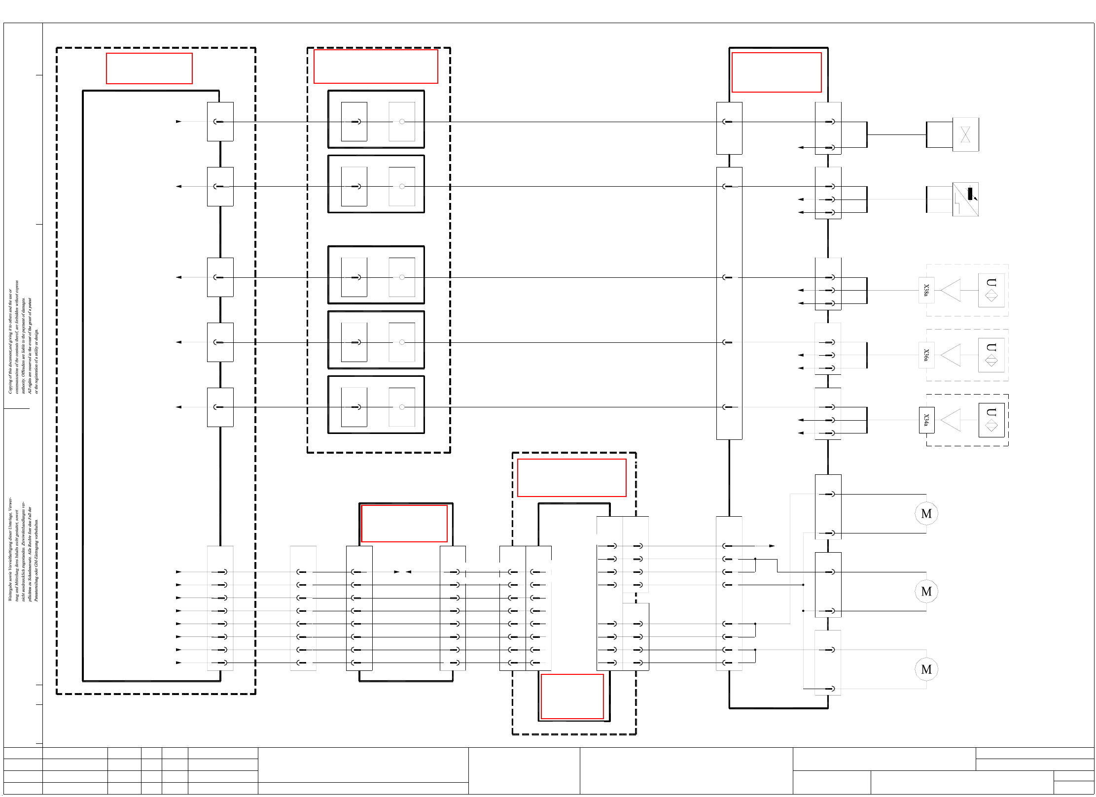
2 SIPLACE 80S-20 Detailed Circuit Diagrams 33
LP6-S20 PCB conveyor 2, conveyor motor control
11
10
7
8
13,14
1,2,3,4
12
1,2,3,4
13,14
9
8
7
12
11
10
Port A5.4
Port A5.5
Port A5.6
Port A5.7
I/O boards
Port A1.5
Port E1.2
Port E4.7
Port E3.7
Port E4.5
00344265-xx
Terminal panel, left-hand side
Valve 'Extend stopper 2'
Sensor switch 'Stopper 2 retracted'
Sonar switch 'output conveyor 2'
Sonar switch 'center conveyor 2'
Sonar switch 'input conveyor 2'
2
3
4
18
19,20
1
17
X7
7,9,10
X1:4
GND
Output conveyor 2
17a
18b
18a
Input conveyor 2
GND
20
21
22
11
12
19
X2c
board
00325460-xx
X5
13,14
1,2,3,4
10
12
X21
2
-wh
+br
6
X23
2
output conveyor 2
00326054-xx
Conveyor motor,
Conveyor motor,
center conveyor 2
00326053-xx
Conveyor motor,
input conveyor 2
00326052-xx
GND
+24VDC
bn
bk
bl
GND
6
+24VDC
X37
3
2
bn
bk
bl
GND
6
+24VDC
X39
3
2
bn
bk
bl
GND
6
+24VDC
X41
3
2
bk
bl
GND
6
X43
2
(Cable)
00327658-xx
Sonar switch,
00326041-xx
input conveyor 2
00327659-xx
(Cable)
center conveyor 2
Sonar switch,
00326042-xx
00327660-xx
(Cable)
output conveyor 2
Sonar switch,
00326043-xx
bn
bl -
+
bk A1
stopper 2
00326044-xx
Sensor switch,
X1c
+30VDC switched
Center conveyor 2
X5'
17b
31a
32b/a
31b
26b,27b/a
X2sg
Port A5.2
GND
+24VDC
Port A5.3
00324087-xx
Control unit
(Cable)
00321505-xx
00326067-xx
(Cable)
6
2
X19
-wh
+br
bn
bk
bl
6
3
X35
2
-wh
+br
6
+br
-wh
Valve,
00326045-xx
stopper 2
gr-pk
11
X13
(Cable)
00326068-xx
gn
3
X12
13
9
11
wh-gn
bk
gr-pk
Conversion board
'dual conveyor'
00325581-xx
6
X2ka
10
X2se
10
X1ka
00321497-xx
(Cable)
A1
A1
(Cable)
00321499-xx
7
X4se
7
X1kb
3
X2kb
00326069-xx
(Cable)
A4
(Cable)
00321504-xx
12
X5sf
11
X2kg
8
X6kg
00326069-xx
(Cable)
A3
(Cable)
00321503-xx
12
X4sf
12
X1kf
8
X2kf
00326069-xx
(Cable)
A4
(Cable)
00321504-xx
10
X5sf
10
X2kg
6
X6kg
00326069-xx
(Cable)
9
11
9
8
7
20
22
21
19
12
11
13,14,23,24
1,2,3,4,16,17,18
X6
switched
GND
Center conv. 2 'slow'
Center conv. 2 'fast'
Output conv. 2 'slow'
Output conv. 2 'fast'
Input conv. 2 'slow'
Input conv. 2 'fast'
dual conveyor
00325581-xx
Conversion board
halfbridge
6-channel
(Cable)
00331297-xx00329285-xx
(Cable)
X1c
11a
10b
11b
10a
6a
6b
1a/b,2a/b,8a,9a/b
7b/a,12b/a
X4c
1,3,4
11
12
13,14
1
2
3
4
00327615-xx
dual conveyor
Control unit -
+30VDC
+24VDC
X3c
Sheet
Sh.
02.
01.
01. 18.03.02
Doc. status
Hi
18.03.02
18.03.02
Product status
Function status
Hi
Hi
18.03.02
LP6-020101LD3
Status Modified Date Name Stand.
Check.
Date
Author
CAD file:
Orig./Repl.f/Replaced by
Mat. no.:
LP6-S20.DWG
Stromlaufplan/Circuit diagram
SD EA
Hi
SIEMENS
SMD Placement System SIPLACE 80S20
1
1
PCB conveyor 2
Conveyor motors control
See page 64 See page 85
See page 126
See page 94
See page 126
See page 124
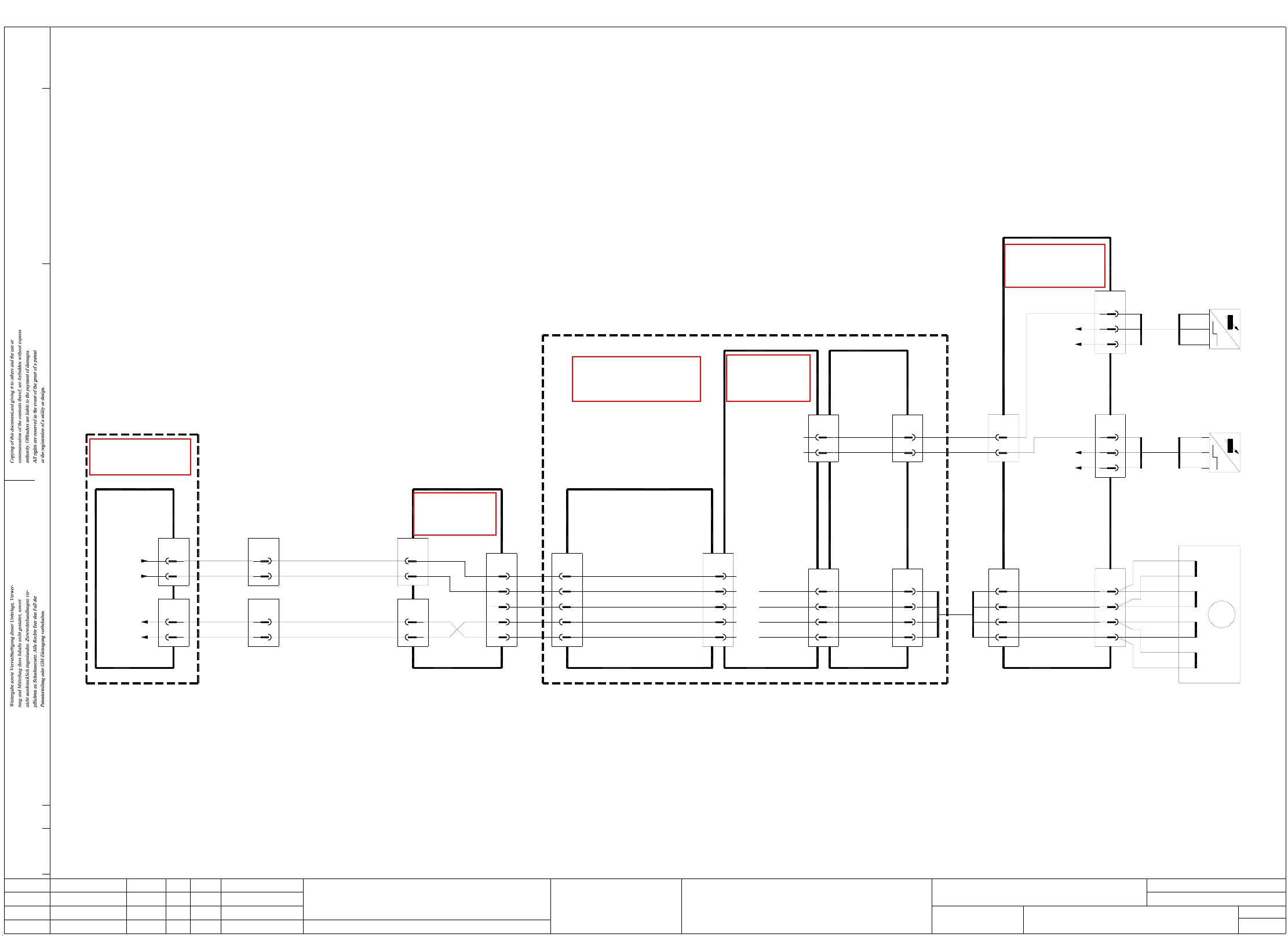
2 SIPLACE 80S-20 Detailed Circuit Diagrams 34
LP7-S20 PCB conveyor 2, lifting table control
bn
GND
10
X10
+24VDC
X29
2
3
6
bk
bn
bl
lifting table 2 bottom
Sensor switch,
00326039-xx
bk
bn
bl
A1
+
-
'dual conveyor'
Conversion board
00325581-xx
+24VDC
GND
6
3
bl
bn
X27
2
bk
lifting table 2 top
Sensor switch,
bl
bn
-
+
00326038-xx
bk A1
X15
2
3
1
orwh
rd
or
4
bn
brwh
rdwh
yewh
ye
lifting table 2
00326058-01
Motor
+
-
-
+
+
-
-
+
A
A
B
B
M
12
X11
6
5
7
8
wh
ye
gn
Stroke 2 B+
Stroke 2 A-
Stroke 2 B-
Stroke 2 A+
'Dual conveyor'
X4
5
6
X5
5
6
X4'
X5'
6
5
5
6
conveyor 2
Lifting table 2 down
Lifting table 2 up
conveyor 2
Lifting table 2 top
Lifting table 2 bottom
End signal
End signal
00329285-xx
(Cable)
(Cable)
00329284-xx
Port E5.1
Port E5.0
X4sg
6
X2sg
6
5
5
I/O cards
Port A5.1
Port A5.0
00321505-xx
(Cable)
00321507-xx
(Cable)
00326062-xx
(Cable) (Cable)
00326065-xx
Control unit
00324087-xx
dual conveyor
Control unit -
00327615-xx
Sheet
Sh.
Status Modified Date Name Stand.
Check.
Date
Author
CAD file:
Orig./Repl.f/Replaced by
Mat. no.:
02.
01.
01. 18.03.02
Doc. status
Hi
18.03.02
18.03.02
Product status
Function status
Hi
Hi
18.03.02
LP7-020101LD3
LP7-S20.DWG
Stromlaufplan/Circuit diagram
SD EA
Hi
SIEMENS
SMD Placement System SIPLACE 80S20
1
1
PCB conveyor 2
Lifting table control
10a,10c
8a,8c
6a,6c
4a,4c
X2b
X1b
18a
17a
4
3
2
1
X4b
12
X3b
10
00325580-xx
Dual stepping
Backplane
wh
bn
gn
ye
motor board
Stroke 2 B+
Stroke 2 B-
Stroke 2 A+
Stroke 2 A-
Sensor switch
Lifting table bottom
Sensor switch
Lifting table top
14c
22a
X1b
13c
14a
Dual stepping
00325579-xx
motor board
22c
X3b
20
19
4
5
3
Dual stepping
00325580-xx
Backplane
motor board
Lifting table 2 down
Lifting table 2 fast/slow
End signal, lifting table 2 bottom
End signal, lifting table 2 top
Lifting table 2 up
00326065-xx
(Cable)
X10
20
19
4
5
3
Conversion board
00325581-xx
See page 64
See page 126
See page 126
See page 94 See page 125