80S20 circuit.pdf - 第4页
SIPLACE 80S-20 Detailed Circuit Diagrams Folder 05/2002 US Edition Table of Contents 4 00324087-070 101TD3 80S-20 control unit (viewed from the front) . . . . . . . . . . . . . . . . . . . . . . . . . . . . . . . . . 64 …

SIPLACE 80S-20 Detailed Circuit Diagrams Folder
05/2002 US Edition
Table of Contents 3
Table of Contents
1 Electrical Symbols and Drawing Numbering System
1.1 Legende/Symbols. . . . . . . . . . . . . . . . . . . . . . . . . . . . . . . . . . . . . . . . . . . . . . . . . . . . . . . . . . . . . . . . . . . . 5
1.1.1 Arten von Strömen und Spannungen / Kind of current and voltage . . . . . . . . . . . . . . . . . . . . . . . . . . . . . . 5
1.1.2 Impulsformen / Signal waveforms . . . . . . . . . . . . . . . . . . . . . . . . . . . . . . . . . . . . . . . . . . . . . . . . . . . . . . . 5
1.1.3 Mechanische Stellteile / Mechanical controls . . . . . . . . . . . . . . . . . . . . . . . . . . . . . . . . . . . . . . . . . . . . . . . 5
1.1.4 Antriebsarten / Operating devices and methods . . . . . . . . . . . . . . . . . . . . . . . . . . . . . . . . . . . . . . . . . . . . 5
1.1.5 Erde, Masse, Äquipotential /
Earth and frame connections, equipotentiality . . . . . . . . . . . . . . . . . . . . . . . . . . . . . . . . . . . . . . . . . . . . . . 6
1.1.6 Leiter / Conductors . . . . . . . . . . . . . . . . . . . . . . . . . . . . . . . . . . . . . . . . . . . . . . . . . . . . . . . . . . . . . . . . . . . 6
1.1.7 Anschlüsse und Leiterverbindungen /
Terminals and connections of conductors . . . . . . . . . . . . . . . . . . . . . . . . . . . . . . . . . . . . . . . . . . . . . . . . . 6
1.1.8 Verbinder / Connecting devices . . . . . . . . . . . . . . . . . . . . . . . . . . . . . . . . . . . . . . . . . . . . . . . . . . . . . . . . . 6
1.1.9 Widerstände / Resistors . . . . . . . . . . . . . . . . . . . . . . . . . . . . . . . . . . . . . . . . . . . . . . . . . . . . . . . . . . . . . . . 7
1.1.10 Kondensatoren / Capacitors . . . . . . . . . . . . . . . . . . . . . . . . . . . . . . . . . . . . . . . . . . . . . . . . . . . . . . . . . . . . 7
1.1.11 Induktivitäten / Inductors. . . . . . . . . . . . . . . . . . . . . . . . . . . . . . . . . . . . . . . . . . . . . . . . . . . . . . . . . . . . . . . 7
1.1.12 Besondere Kennzeichen für Halbleiterelemente /
Qualifying symbols particular to semiconductor devices . . . . . . . . . . . . . . . . . . . . . . . . . . . . . . . . . . . . . . 7
1.1.13 Beispiele für Halbleiterdioden / Examples of semiconductor diodes . . . . . . . . . . . . . . . . . . . . . . . . . . . . . 7
1.1.14 Beispiele für Transistoren / Examples of transistors . . . . . . . . . . . . . . . . . . . . . . . . . . . . . . . . . . . . . . . . . 8
1.1.15 Beispiele für licht- und magnetfeldempfindliche Elemente /
Examples of photo-sensitive and magnetic field sensitive devices . . . . . . . . . . . . . . . . . . . . . . . . . . . . . . 8
1.1.16 Intern verbundene Wicklungen / Internally connected windings. . . . . . . . . . . . . . . . . . . . . . . . . . . . . . . . . 8
1.1.17 Maschinenarten / Types of machines. . . . . . . . . . . . . . . . . . . . . . . . . . . . . . . . . . . . . . . . . . . . . . . . . . . . . 8
1.1.18 Allgemeine Symbole / General symbols. . . . . . . . . . . . . . . . . . . . . . . . . . . . . . . . . . . . . . . . . . . . . . . . . . . 8
1.1.19 Beispiele für Transformatoren mit getrennten Wicklungen /
Examples of transformers with separate windings . . . . . . . . . . . . . . . . . . . . . . . . . . . . . . . . . . . . . . . . . . . 8
1.1.20 Blocksymbole für Leistungsumrichter /
Block symbols for power converters. . . . . . . . . . . . . . . . . . . . . . . . . . . . . . . . . . . . . . . . . . . . . . . . . . . . . . 9
1.1.21 Primärzellen und Akkumulatoren / Primary cells and accumulators. . . . . . . . . . . . . . . . . . . . . . . . . . . . . . 9
1.1.22 Kontakte mit zwei oder drei Schaltstellungen /
Contacts with two or three positions. . . . . . . . . . . . . . . . . . . . . . . . . . . . . . . . . . . . . . . . . . . . . . . . . . . . . . 9
1.1.23 Voreilende und nacheilende Kontakte / Early and late operating contacts . . . . . . . . . . . . . . . . . . . . . . . . 9
1.1.24 Handbetätigte Schalter / Single-pole switches . . . . . . . . . . . . . . . . . . . . . . . . . . . . . . . . . . . . . . . . . . . . . . 9
1.1.25 Elektromechanische Antriebe / Operating devices. . . . . . . . . . . . . . . . . . . . . . . . . . . . . . . . . . . . . . . . . . . 9
1.1.26 Sicherungen und Sicherungsschalter / Fuses and fuse-switches . . . . . . . . . . . . . . . . . . . . . . . . . . . . . . . 9
1.1.27 Leuchtmelder und Signaleinrichtungen / Lamps and signalling devices . . . . . . . . . . . . . . . . . . . . . . . . . 10
1.1.28 Verstärker / Amplifiers . . . . . . . . . . . . . . . . . . . . . . . . . . . . . . . . . . . . . . . . . . . . . . . . . . . . . . . . . . . . . . . 10
1.2 Structure of the Technical Numbering System . . . . . . . . . . . . . . . . . . . . . . . . . . . . . . . . . . . . . . . . . . . . . 11
2 SIPLACE 80S-20 Detailed Circuit Diagrams
NOTS20-1 EMERG.-STOP circuit, SIPLACE 80S-20. . . . . . . . . . . . . . . . . . . . . . . . . . . . . . . . . . 12
NOTS20-2 EMERG.-STOP circuit - signaling circuit - SIPLACE 80S-20 . . . . . . . . . . . . . . . . . . . 13
X1-S20 X-axis, gantry 1, SIPLACE 80S-20 . . . . . . . . . . . . . . . . . . . . . . . . . . . . . . . . . . . . . . . 14
X2-S20 X-axis, gantry 2, SIPLACE 80S-20 . . . . . . . . . . . . . . . . . . . . . . . . . . . . . . . . . . . . . . . 15
Y1-S20 Y-axis, gantry 1, SIPLACE 80S-20 . . . . . . . . . . . . . . . . . . . . . . . . . . . . . . . . . . . . . . . 16
Y2-S20 Y-axis, gantry 2, SIPLACE 80S-20 . . . . . . . . . . . . . . . . . . . . . . . . . . . . . . . . . . . . . . . 17
DR1-S20 12-segment Collect&Place head / star-axis, gantry 1, SIPLACE 80S-20 . . . . . . . . . .18
DR2-S20 12-segment Collect&Place head / star-axis, gantry 2, SIPLACE 80S-20 . . . . . . . . . .19
Z1-S20 12-segment Collect&Place head / Z-axis, gantry 1, SIPLACE 80S-20 . . . . . . . . . . . .20
Z2-S20 12-segment Collect&Place head / Z-axis, gantry 2, SIPLACE 80S-20 . . . . . . . . . . . .21
DP1-S20 12-segment Collect&Place head / DP-axis, gantry 1, SIPLACE 80S-20 . . . . . . . . . . .22
DP2-S20 12-segment Collect&Place head / DP-axis, gantry 2, SIPLACE 80S-20 . . . . . . . . . . .23
ZM1-S20 12-segment Collect&Place head / feed motors / CAN bus, gantry 1 . . . . . . . . . . . . . .24
ZM2-S20 12-segment Collect&Place head / feed motors / CAN bus, gantry 2 . . . . . . . . . . . . . .25
SERVS201 Power supply for servo amplifier, SIPLACE 80S-20 . . . . . . . . . . . . . . . . . . . . . . . . . .26
SERVS202 Power supply for servo amplifier, SIPLACE 80S-20 . . . . . . . . . . . . . . . . . . . . . . . . . .27
LP1-S20 PCB conveyor 1 + 2, power supply . . . . . . . . . . . . . . . . . . . . . . . . . . . . . . . . . . . . . . .28
LP2-S20 PCB conveyor 1, conveyor motor control . . . . . . . . . . . . . . . . . . . . . . . . . . . . . . . . . .29
LP3-S20 PCB conveyor 1, lifting table control . . . . . . . . . . . . . . . . . . . . . . . . . . . . . . . . . . . . . .30
LP4-S20 PCB conveyor 1, width adjustment . . . . . . . . . . . . . . . . . . . . . . . . . . . . . . . . . . . . . . .31
LP5-S20 Ceramic substrate centering . . . . . . . . . . . . . . . . . . . . . . . . . . . . . . . . . . . . . . . . . . . .32
LP6-S20 PCB conveyor 2, conveyor motor control . . . . . . . . . . . . . . . . . . . . . . . . . . . . . . . . . .33
LP7-S20 PCB conveyor 2, lifting table control . . . . . . . . . . . . . . . . . . . . . . . . . . . . . . . . . . . . . .34
LP8-S20 PCB conveyor 2, width adjustment . . . . . . . . . . . . . . . . . . . . . . . . . . . . . . . . . . . . . . .35
LP9-S20 PCB conveyor 2, ceramic substrate centering. . . . . . . . . . . . . . . . . . . . . . . . . . . . . . .36
BT1-S20 Component table, mobile, right-hand side . . . . . . . . . . . . . . . . . . . . . . . . . . . . . . . . . .37
BT2-S20 Component table, mobile, left-hand side . . . . . . . . . . . . . . . . . . . . . . . . . . . . . . . . . . .38
GS1-S20 Tape cutter, pneumatically operated, right-hand side . . . . . . . . . . . . . . . . . . . . . . . . .39
GS2-S20 Tape cutter, pneumatically operated, left-hand side . . . . . . . . . . . . . . . . . . . . . . . . . .40
PW1-S20 Nozzle changer . . . . . . . . . . . . . . . . . . . . . . . . . . . . . . . . . . . . . . . . . . . . . . . . . . . . . .41
3 SIPLACE 80S-20 Circuit Diagrams
00116950-010101LD3 Z-diagram, gantry 1 (Sh. 1 of 7). . . . . . . . . . . . . . . . . . . . . . . . . . . . . . . . . . . . . . . . . .42
00116950-010101LD3 Z-diagram, gantry 2 (Sh. 2 of 7). . . . . . . . . . . . . . . . . . . . . . . . . . . . . . . . . . . . . . . . . .43
00116950-010101LD3 Z-diagram, power supply (Sh. 3 of 7). . . . . . . . . . . . . . . . . . . . . . . . . . . . . . . . . . . . . .44
00116950-010101LD3 Z-diagram, machine wiring 1 (Sh. 4 of 7). . . . . . . . . . . . . . . . . . . . . . . . . . . . . . . . . . .45
00116950-010101LD3 Z-diagram, machine wiring 2 (Sh. 5 of 7). . . . . . . . . . . . . . . . . . . . . . . . . . . . . . . . . . .46
00116950-010101LD3 Z-diagram, PCB conveyor 1 (Sh. 6 of 7) . . . . . . . . . . . . . . . . . . . . . . . . . . . . . . . . . . .47
00116950-010101LD3 Z-diagram, PCB conveyor 2 (Sh. 7 of 7) . . . . . . . . . . . . . . . . . . . . . . . . . . . . . . . . . . .48
00116900-020101FD3 Input/output assignment, SIPLACE 80S20 (Sh. 1 of 2) . . . . . . . . . . . . . . . . . . . . . . . .49
00116900-020101FD3 Input/output assignment, SIPLACE 80S20 (Sh. 2 of 2) . . . . . . . . . . . . . . . . . . . . . . . .50
00321086-050101FD3 SIPLACE 80S20/F4 safety concept (power unit) (Sh. 1 of 3) . . . . . . . . . . . . . . . . . . .51
00321086-050101FD3 Siplace 80S20/F4 safety concept overview (safety circuit) (Sh. 2 of 3) . . . . . . . . . . . .52
00321086-050101FD3 Siplace 80S20/F4 safety concept overview (signaling circuit) (Sh. 3 of 3) . . . . . . . . .53
00321086-050101LD3 SIPLACE 80S20/F4 power supply (Sh. 1 of 2) . . . . . . . . . . . . . . . . . . . . . . . . . . . . . .54
00321086-050101LD3 SIPLACE 80S20/F4 power supply (Sh. 2 of 2) . . . . . . . . . . . . . . . . . . . . . . . . . . . . . .55
00321086-050101TD3 Power supply (Sh. 1 of 4). . . . . . . . . . . . . . . . . . . . . . . . . . . . . . . . . . . . . . . . . . . . . . .56
00321086-050101TD3 Power supply (Sh. 2 of 4). . . . . . . . . . . . . . . . . . . . . . . . . . . . . . . . . . . . . . . . . . . . . . .57
00321086-050101TD3 Power supply (Sh. 3 of 4). . . . . . . . . . . . . . . . . . . . . . . . . . . . . . . . . . . . . . . . . . . . . . .58
00321086-050101TD3 Power supply (Sh. 4 of 4). . . . . . . . . . . . . . . . . . . . . . . . . . . . . . . . . . . . . . . . . . . . . . .59
00300272-050101LD3 Service socket . . . . . . . . . . . . . . . . . . . . . . . . . . . . . . . . . . . . . . . . . . . . . . . . . . . . . . .60
00300272-050101TD3 Service socket . . . . . . . . . . . . . . . . . . . . . . . . . . . . . . . . . . . . . . . . . . . . . . . . . . . . . . .61
00324087-070101LD3 80S-20 control unit (Sh. 1 of 2) . . . . . . . . . . . . . . . . . . . . . . . . . . . . . . . . . . . . . . . . . .62
00324087-070101LD3 80S-20 control unit (Sh. 2 of 2) . . . . . . . . . . . . . . . . . . . . . . . . . . . . . . . . . . . . . . . . . .63

SIPLACE 80S-20 Detailed Circuit Diagrams Folder
05/2002 US Edition
Table of Contents 4
00324087-070101TD3 80S-20 control unit (viewed from the front). . . . . . . . . . . . . . . . . . . . . . . . . . . . . . . . . 64
00347286-010101FD4 Control unit (wrap connections) (Sh. 1 of 3) . . . . . . . . . . . . . . . . . . . . . . . . . . . . . . . . 65
00347286-010101FD4 Control unit (wrap connections) (Sh. 2 of 3) . . . . . . . . . . . . . . . . . . . . . . . . . . . . . . . . 65
00347286-010101FD4 Control unit (wrap connections) (Sh. 3 of 3) . . . . . . . . . . . . . . . . . . . . . . . . . . . . . . . . 66
00347286-010101TD3 Control unit S20B/F4B, basic module, (viewed from the front) (Sh. 1 of 2) . . . . . . . . 67
00347286-010101TD3 Control unit S20B/F4B, basic module, (viewed from the back) (Sh. 2 of 2) . . . . . . . . 68
00321480-020701LD3 80S20 servo unit (Sh. 1 of 2) . . . . . . . . . . . . . . . . . . . . . . . . . . . . . . . . . . . . . . . . . . . 69
00321480-020701LD3 80S20 servo unit (Sh. 2 of 2) . . . . . . . . . . . . . . . . . . . . . . . . . . . . . . . . . . . . . . . . . . . 70
00321480-020701TD3 Servo unit, viewed from the front (Sh. 1 of 2) . . . . . . . . . . . . . . . . . . . . . . . . . . . . . . . 71
00321480-020701TD3 80S20 servo unit (Sh. 2 of 2) . . . . . . . . . . . . . . . . . . . . . . . . . . . . . . . . . . . . . . . . . . . 72
00321693-030201LD3 Circuit diagram, 80S-20 servo unit, basic module (Sh. 1 of 4) . . . . . . . . . . . . . . . . . . 73
00321693-030201LD3 Circuit diagram, 80S-20 servo unit, basic module (Sh. 2 of 4) . . . . . . . . . . . . . . . . . . 74
00321693-030201LD3 80S-20 servo unit, basic module, power supply (Sh. 3 of 4). . . . . . . . . . . . . . . . . . . . 75
00321693-030201LD3 80S-20 servo unit, basic module, power supply (Sh. 4 of 4). . . . . . . . . . . . . . . . . . . . 76
00321693-030101TD3 80S20 servo unit, basic module, plug assignment (Sh. 1 of 3). . . . . . . . . . . . . . . . . . 77
00321693-030101TD3 80S20 servo unit, basic module, viewed from the front (Sh. 2 of 3) . . . . . . . . . . . . . . 78
00321693-030101TD3 80S20 servo unit, basic module, viewed from the back (Sh. 3 of 3) . . . . . . . . . . . . . . 79
00321785-020102LD3 Potential distributor board . . . . . . . . . . . . . . . . . . . . . . . . . . . . . . . . . . . . . . . . . . . . . . 80
00321510-070201LD3 Terminal panel (right-hand side) (voltage rectification). . . . . . . . . . . . . . . . . . . . . . . . 81
00321510-070201TD3 Terminal panel (right-hand side). . . . . . . . . . . . . . . . . . . . . . . . . . . . . . . . . . . . . . . . . 82
00344265-020101LD3 Terminal panel (left-hand side) (Sh. 1 of 2) . . . . . . . . . . . . . . . . . . . . . . . . . . . . . . . . 83
00344265-020101LD3 Terminal panel (left-hand side) (Sh. 2 of 2) . . . . . . . . . . . . . . . . . . . . . . . . . . . . . . . . 84
00344265-020101TD3 Terminal panel (left-hand side) . . . . . . . . . . . . . . . . . . . . . . . . . . . . . . . . . . . . . . . . . . 85
00200034-040101LD3 Optical decoupling unit . . . . . . . . . . . . . . . . . . . . . . . . . . . . . . . . . . . . . . . . . . . . . . . . 86
00116046-020101LD4 Siplace 80S20/F4, single conveyor, stationary side, left-hand side/right-hand side. . 87
00331465-010101TD3 Control unit, single conveyor (viewed from the front/back),
assemblies overview (Sh. 1 of 2) . . . . . . . . . . . . . . . . . . . . . . . . . . . . . . . . . . . . . . . . 88
00331465-010101TD3 Control unit, single conveyor, (viewed from the front/back),
assemblies overview (Sh. 2 of 2) . . . . . . . . . . . . . . . . . . . . . . . . . . . . . . . . . . . . . . . . 89
00328647-010101LD3 Tape cutter, max. tape height 15 mm . . . . . . . . . . . . . . . . . . . . . . . . . . . . . . . . . . . . . 90
00116226-010101LD3 Component table, mobile . . . . . . . . . . . . . . . . . . . . . . . . . . . . . . . . . . . . . . . . . . . . . . 91
4 80S-20/OPTIONS Circuit Diagrams
00303636-020101LD3 Cable connecting SIPLACE stations. . . . . . . . . . . . . . . . . . . . . . . . . . . . . . . . . . . . . . 92
00116025-020101LD3 Dual conveyor, stationary side left-hand side/right-hand side . . . . . . . . . . . . . . . . . . 93
00327615-020101TD3 Control unit, dual conveyor (viewed from the front/back) (assemblies overview) . . . . 94
00117185-010101FD4 110/208V conversion kit for SIPLACE 80 S20 / S23 / F4 / F5 (Sh. 1 of 2) . . . . . . . . . 95
00117185-010101FD4 110/208V conversion kit for SIPLACE 80 S20 / S23 / F4 / F5 (Sh. 2 of 2) . . . . . . . . . 95
00117185-010101LD3 110/208V conversion kit for SIPLACE 80 S20 / S23 / F4 / F5 (Sh. 1 of 3) . . . . . . . . . 96
00117185-010101LD3 110/208V conversion kit for SIPLACE 80 S20 / S23 / F4 / F5 (Sh. 2 of 3) . . . . . . . . . 97
00117185-010101LD3 110/208V conversion kit for SIPLACE 80 S20 / S23 / F4 / F5 (Sh. 3 of 3) . . . . . . . . . 98
00116161-020102LD4 Nozzle changer for Collect&Place head 80S-20/F4 (Sh. 1 of 2). . . . . . . . . . . . . . . . . 99
00116161-020102LD4 Nozzle changer for Collect&Place head 80S-20/F4 (Sh. 2 of 2). . . . . . . . . . . . . . . . . 99
00347474-010102LD4 PCB barcode, top/bottom . . . . . . . . . . . . . . . . . . . . . . . . . . . . . . . . . . . . . . . . . . . . . 100
00343635-010101LD4 PCB barcode distributor board . . . . . . . . . . . . . . . . . . . . . . . . . . . . . . . . . . . . . . . . . 101
00343635-010101ND4 886 PCB, distributor - PCB barcode . . . . . . . . . . . . . . . . . . . . . . . . . . . . . . . . . . . . . 101
00345332-010101LD4 Cable: power supply, PCB barcode . . . . . . . . . . . . . . . . . . . . . . . . . . . . . . . . . . . . . 102
00345333-010101LD4 Cable: PCB barcode distributor - MC . . . . . . . . . . . . . . . . . . . . . . . . . . . . . . . . . . . . 103
5 SIPLACE 80S-20 Printed Circuit Boards
00200034-040101ND4 871 PCB, signal decoupling unit . . . . . . . . . . . . . . . . . . . . . . . . . . . . . . . . . . . . . . . .104
00300167-020101ND4 Recitifier board, 30V . . . . . . . . . . . . . . . . . . . . . . . . . . . . . . . . . . . . . . . . . . . . . . . . .104
00300168-020101ND4 Recitifier board, 6V . . . . . . . . . . . . . . . . . . . . . . . . . . . . . . . . . . . . . . . . . . . . . . . . . .105
00300169-020101ND4 Recitifier board, 60V . . . . . . . . . . . . . . . . . . . . . . . . . . . . . . . . . . . . . . . . . . . . . . . . .105
00300398-030105ND4 Gantry distributor board . . . . . . . . . . . . . . . . . . . . . . . . . . . . . . . . . . . . . . . . . . . . . . .106
00308443-050101ND4 Discharge board. . . . . . . . . . . . . . . . . . . . . . . . . . . . . . . . . . . . . . . . . . . . . . . . . . . . .106
00319076-020102ND3 Axis rear panel (axis 166) . . . . . . . . . . . . . . . . . . . . . . . . . . . . . . . . . . . . . . . . . . . . .107
00320854-020202MD4 745 PCB, backplane-servo unit Y1002 . . . . . . . . . . . . . . . . . . . . . . . . . . . . . . . . . . .108
00320855-010202MD4 Backplane-servo unit Y1003 . . . . . . . . . . . . . . . . . . . . . . . . . . . . . . . . . . . . . . . . . . .108
00321036-010101FD4 Axis rear panel I (axis 166) . . . . . . . . . . . . . . . . . . . . . . . . . . . . . . . . . . . . . . . . . . . .109
00321037-010101FD4 Axis rear panel II (axis 166) . . . . . . . . . . . . . . . . . . . . . . . . . . . . . . . . . . . . . . . . . . . .109
00321189-030101ND4 820 PCB, conversion board, large axis (Sh. 1 of 2). . . . . . . . . . . . . . . . . . . . . . . . . .110
00321189-030101ND4 820 PCB, conversion board, large axis (Sh. 2 of 2). . . . . . . . . . . . . . . . . . . . . . . . . .110
00321190-030101ND3 Gantry conversion board . . . . . . . . . . . . . . . . . . . . . . . . . . . . . . . . . . . . . . . . . . . . . .111
00321213-040101ND4 Adjustment unit, SP6_12 placement head. . . . . . . . . . . . . . . . . . . . . . . . . . . . . . . . .112
00321214-090101ND3 SP6_12 head board (Sh. 1 of 2) . . . . . . . . . . . . . . . . . . . . . . . . . . . . . . . . . . . . . . . .113
00321214-090101ND3 SP6_12 head board (Sh. 2 of 2) . . . . . . . . . . . . . . . . . . . . . . . . . . . . . . . . . . . . . . . .114
00321215-080101ND3 SP6-12 adapter board . . . . . . . . . . . . . . . . . . . . . . . . . . . . . . . . . . . . . . . . . . . . . . . .115
00321469-040101ND3 Vision assembly . . . . . . . . . . . . . . . . . . . . . . . . . . . . . . . . . . . . . . . . . . . . . . . . . . . . .116
00321470-030101ND4 740 PCB, three-phase current for star-axis (Sh. 1 of 2). . . . . . . . . . . . . . . . . . . . . . .117
00321470-030101ND4 740 PCB, three-phase current for star-axis (Sh. 2 of 2). . . . . . . . . . . . . . . . . . . . . . .117
00321524-040101ND4 Sensor, Z-axis, bottom. . . . . . . . . . . . . . . . . . . . . . . . . . . . . . . . . . . . . . . . . . . . . . . .118
00321525-020102ND4 Component illumination . . . . . . . . . . . . . . . . . . . . . . . . . . . . . . . . . . . . . . . . . . . . . . .118
00322100-030102ND4 Anticrash board . . . . . . . . . . . . . . . . . . . . . . . . . . . . . . . . . . . . . . . . . . . . . . . . . . . . .119
00322333-010304MD4 Video multiplexer, manually controlled . . . . . . . . . . . . . . . . . . . . . . . . . . . . . . . . . . .119
00322822-030101ND3 Servo controller, component mounting diagram . . . . . . . . . . . . . . . . . . . . . . . . . . . .120
00323583-030101ND3 SMD component table control board (Sh. 1 of 2). . . . . . . . . . . . . . . . . . . . . . . . . . . .121
00323583-030101ND3 SMD component table control board (Sh. 2 of 2). . . . . . . . . . . . . . . . . . . . . . . . . . . .122
00323584-010202ND3 Component table conversion board . . . . . . . . . . . . . . . . . . . . . . . . . . . . . . . . . . . . . .123
00325460-010101ND4 774 PCB, half bridge board . . . . . . . . . . . . . . . . . . . . . . . . . . . . . . . . . . . . . . . . . . . .124
00325579-020101ND4 775 PCB, step motor control, power circuit . . . . . . . . . . . . . . . . . . . . . . . . . . . . . . . .125
00325579-020101ND4 776 PCB, step motor control, control unit . . . . . . . . . . . . . . . . . . . . . . . . . . . . . . . . .125
00325581-030101MD4 Conversion board, PCB conveyor . . . . . . . . . . . . . . . . . . . . . . . . . . . . . . . . . . . . . . .126
00326142-070101ND3 KSP-COM351 communications assembly . . . . . . . . . . . . . . . . . . . . . . . . . . . . . . . . .127
00327250-010101MD4 A1 I/O terminal board. . . . . . . . . . . . . . . . . . . . . . . . . . . . . . . . . . . . . . . . . . . . . . . . .128
00327251-010101MD4 A2 I/O terminal board. . . . . . . . . . . . . . . . . . . . . . . . . . . . . . . . . . . . . . . . . . . . . . . . .128
00327252-010101MD4 A3 I/O terminal board. . . . . . . . . . . . . . . . . . . . . . . . . . . . . . . . . . . . . . . . . . . . . . . . .129
00327283-010101MD4 A4 signal decoupling unit . . . . . . . . . . . . . . . . . . . . . . . . . . . . . . . . . . . . . . . . . . . . . .129
00327284-010101MD4 A6 signal decoupling unit . . . . . . . . . . . . . . . . . . . . . . . . . . . . . . . . . . . . . . . . . . . . . .130
00329699-020101ND3 HS50 tape cutter control board (Sh. 1 of 2) . . . . . . . . . . . . . . . . . . . . . . . . . . . . . . . .131
00329699-020101ND3 HS50 tape cutter control board (Sh. 2 of 2) . . . . . . . . . . . . . . . . . . . . . . . . . . . . . . . .132
00330573-010101ND4 DP-motor interference suppression board. . . . . . . . . . . . . . . . . . . . . . . . . . . . . . . . .133
00342582-020101ND3 S23 backplane, component mounting diagram, wired components, side 1. . . . . . . .134
00347857-020101ND4 922 PCB, vacuum board 2 (Sh. 1 of 2) . . . . . . . . . . . . . . . . . . . . . . . . . . . . . . . . . . .135
00347857-020101ND4 922 PCB, vacuum board 2 (Sh. 2 of 2) . . . . . . . . . . . . . . . . . . . . . . . . . . . . . . . . . . .135
6 SIPLACE 80S-20 Pneumatic Diagrams
00329027-010202XD1 SIPLACE 80S-20 pneumatic diagram . . . . . . . . . . . . . . . . . . . . . . . . . . . . . . . . . . . .136
00328647-010201XD3 SIPLACE tape cutter, pneumatically operated. . . . . . . . . . . . . . . . . . . . . . . . . . . . . .137
00329906-010101EX3 Pneumatic symbols . . . . . . . . . . . . . . . . . . . . . . . . . . . . . . . . . . . . . . . . . . . . . . . . . .138
SIPLACE 80S-20 Detailed Circuit Diagrams Folder
05/2002 US Edition
1 Electrical Symbols and Drawing Numbering System 5
1 Electrical Symbols and Drawing Numbering System
1.1 Legende/Symbols
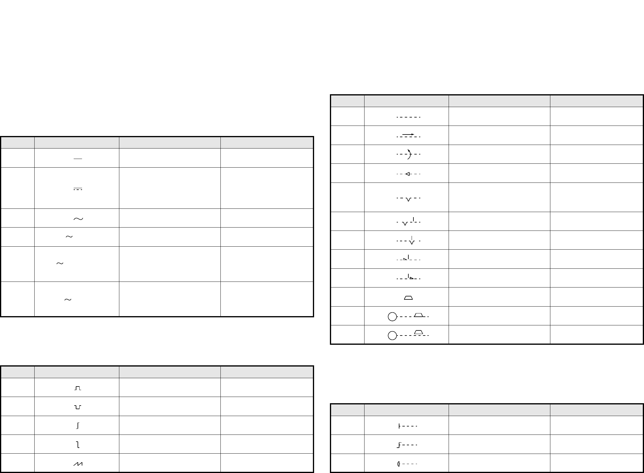
1.1.1 Arten von Strömen und Spannungen / Kind of current and voltage
1.1.2 Impulsformen / Signal waveforms
1.1.3 Mechanische Stellteile / Mechanical controls
1.1.4 Antriebsarten / Operating devices and methods
Nr. / No. Schaltzeichen / Symbol Beschreibung Description
02-02-01 Gleichstrom Direct current
02-02-03
Gleichstrom
Anmerkung:
Das Schaltzeichen 02-02-03 muß ange-
wendet werden, wenn das Schaltzei-
chen 02-02-01 zu Verwechslungen
führt.
Direct current
Note:
Symbol 02-02-03 is to be used if
symbol 02-02-01 causes confusion.
02-02-04 Wechselstrom Alternating current
02-02-05 Wechselstrom, 50 Hz Alternating current of 50 Hz
02-02-07
Dreiphasen-Vierleitersystem mit drei
Außenleitern und einem Neutralleiter,
50 Hz, 400 V (230 V zwischen jedem
Außenleiter und dem Neutralleiter).
3N darf durch 3/N ersetzt werden.
Alternating current: three-phase
with neutral, 50 Hz, 400 V (230 V
between phase and neutral).
3N may be replaced by 3 + N.
02-02-08
Dreiphasen-Fünfleitersystem mit drei
Außenleitern, einem Neutralleiter und
einem Schutzleiter, 50 Hz, direkte
Erdung eines Punktes, Neutral- und
Schutzleiter getrennt.
Alternating current, three-phase, 50
Hz: system having one point directly
earthed and separate neutral and
protective conductors throughout.
Nr. / No. Schaltzeichen / Symbol Beschreibung Description
02-10-01 Positiver Impuls Positive-going pulse
02-10-02 Negativer Impuls Negative-going pulse
02-10-04 Positive Schrittfunktion Positive-going step function
02-10-05 Negative Schrittfunktion Negative-going step function
02-10-06
Sägezahn Saw-tooth
50 Hz
3N 50 Hz 400/230 V
3/N/PE 50 Hz / TN - S
Nr. / No. Schaltzeichen / Symbol Beschreibung Description
02-12-01 Wirkverbindung, allgemein Mechanical connection (link)
02-12-02
Mechanische Verbindung mit Angabe
der Richtung von Kraft oder Bewegung
Mechanical connection with indica-
tion of direction of force or motion
02-12-03
Mechanische Verbindung mit Angabe
der Drehrichtung
Mechanical connection with indica-
tion of direction of rotation
02-12-07 Selbsttätiger Rückgang Automatic return
02-12-08
Raste
Nicht selbsttätiger Rückgang
Einrichtung zum Beibehalten einer
gegebenen Stellung
Detent
Non-automatic return
Device for maintaining a given posi-
tion
02-12-09 Raste, nicht eingerastet Detent, disengaged
02-12-10 Raste, eingerastet Detent, engaged
02-12-12 Sperre, nicht verklinkt Latching device, disengaged
02-12-13 Sperre, verklinkt Latching device, engaged
02-12-20 Bremse Brake
02-12-21 Elektromotor mit eingelegter Bremse Electric motor with brake applied
02-12-22 Elektromotor mit gelöster Bremse Electric motor with brake released
Nr. / No. Schaltzeichen / Symbol Beschreibung Description
02-13-01 Handantrieb, allgemein
Manually operated control,
general symbol
02-13-04 Betätigung durch Drehen Operated by turning
02-13-08 Notschalter
Emergency switch (mushroom-head
safety feature)
M
M