80S20 circuit.pdf - 第84页
3 SIPLACE 80S-20 Circuit Diagrams 84 00344265-020101LD3 T erminal panel (lef t-hand side) (Sh. 2 of 2) wh&br gn&ye bn pk gy ye gn wh gn ye bn wh pk gy GND bus ba r ye bl&rd bk pk gy&pk rd&bl bn wh vio…
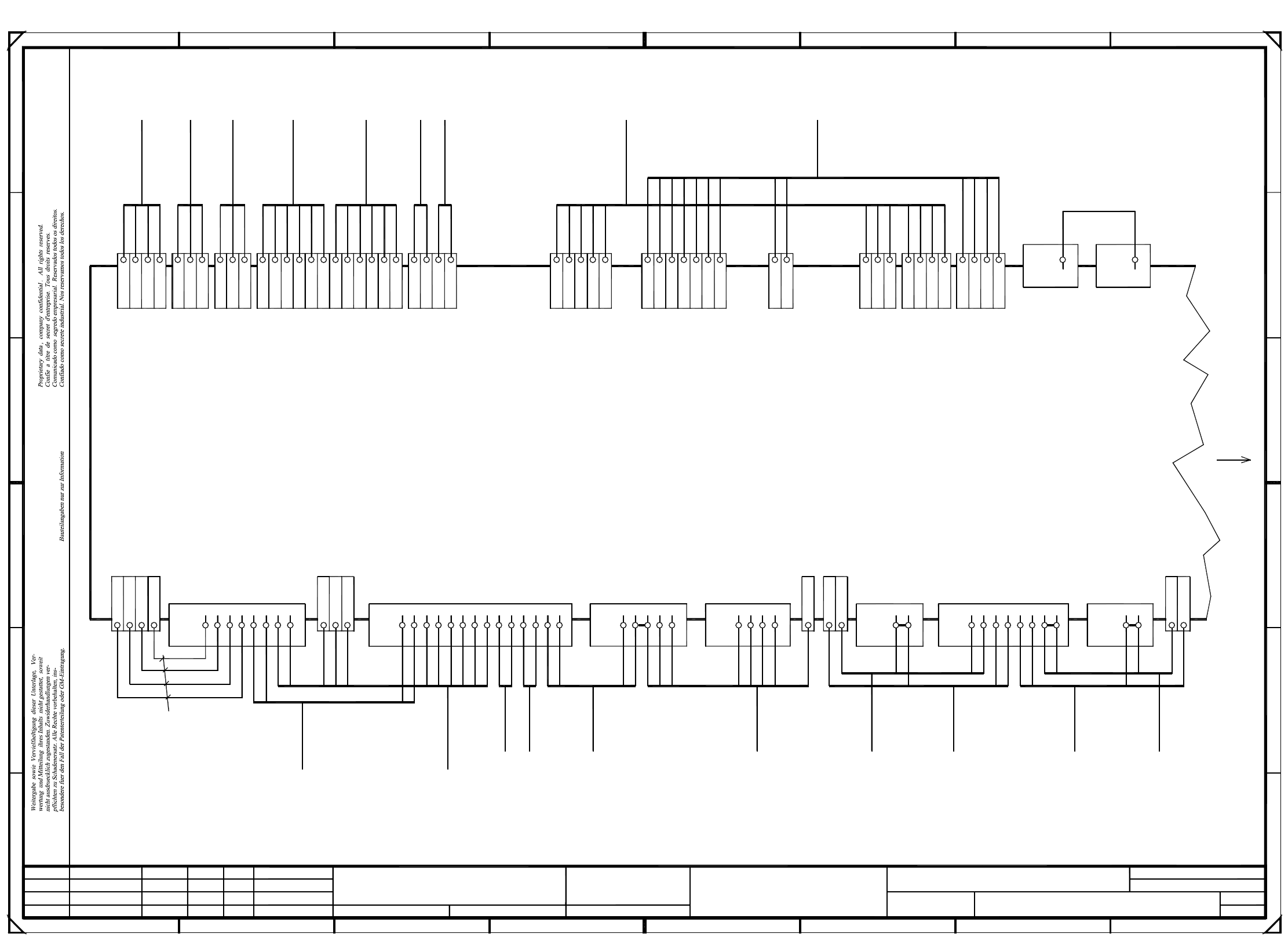
3 SIPLACE 80S-20 Circuit Diagrams 83
00344265-020101LD3 Terminal panel (left-hand side) (Sh. 1 of 2)
=
SIEMENS AG
+
00303614-xx
2
86kg
00322069 00322070
3
(00321421-xx)
2kb
2kb
X210
5kg
2kf
2
X
00321417-xx
00305815-xx
X
3
2kf
2kf
2kf
2ka
7
X2kd +
GND
+2kd
00321573-xx
3
X
X
X
X
00321434-xx
1
00321509-xx
00321529-xx
5
11-12 X211
X
8
2ka
2kf
GND
X
X
5
X
5ki
X5ki
GND
X210
D
2kb
+24V
X212
X
2kf
5
X
7
6
A
B
C
D
C
B
A
7
2
2kc
2kc 3
7
X
2kf
00321528-xx
7
X5ki 8
F
+24V
GND
IcosMC1
M44
X211
1
12
3
16
E
F
19
E
2kf
GND 24V
+24V
6kg
4
315
00322356-xx
00301486-xx
00317579-xx W1
4
+
00305816-xx
X210
3
1
7
16 17
6
X7
X8
2ka
2ka
X
+24V
+24V
+24V
+24V
2kd
311
X211
5ki
17
61 8
818
X211
00317579-xx W2
+
X2kf 2
X
5
2ka
00321433-xx
X211
GND
32
2kb
5
X
8
2kd
18
00321432-xx
+X
2ka
X
5
2kd
5kg 6
X5kg 7
5
6kg
89
00326069-01
10 11
23
X
6
X6
00321416-xx
00321574-xx
5
00321436-xx
00321529-xx
+24V
X
X6kg
192
12
2kd
X
2kf
X
00326068-01
82kb
X+2kd
X+
2kd
X
6
X4
910
34
6
GND
-
X-
X+
X
X
X
2kc
2ka
X
X
GND
GND
7
X
2kb
2kb
X5
-xx
1
-
X2kc
314221 4
2
X1
2kd
GND
2kd
X
X5
2ka
6
2kd
4
00321528-xx
2kd
4
X
X
4
2kc
3
X-
2kf
2kf
X
2kf
6
2kd +24V
X+
-xx
2ka
00321587-xx
00321588-xx
X4
X3
2kd
X
25
00322070-xx
2kf -
+
X
2kc 1
3
-
X2kc 5
X
*(00344226-xx)
*(00344225-xx)
X2kd
2
X
6
00322069-xx
+24V
+24V
+
-
X-
X
01
01
02
Leh
Ha
Ha
11
5
X210
PL EA1 E5
00344265-020101LD3
#
Haas
02.09.99
02.10.98
02.09.99
02.09.99
Date
Check.
Author
Creat. byCreat. f.Orig.NameModified DateStatus Stand.
Sh.
Sheet
SMD Placement System SIPLACE 80S20/S23
Document status
Product status
Function status
Circuit diagram, terminal panel
lefthand side
Emerg.-stop button
Start button
Cover open
From signaling circuit, Emerg.-stop button
From signaling circuit, Start button
+24V (CO-table 1-4)
From control circuit, Stop button
Keyswitch
From feeder crash sensor, left CO-table, S1
From control circuit, Emerg.-stop button
To control circuit, Emerg-stop button
To control circuit, Emerg.-stop button
To control circuit, Emerg.-stop button
To control circuit 1, START button
From control circuit 1, START button
To control circuit 2, START button
From control circuit 2, START button
To keyswitch
From CO-table (E-S-L)
From keyswitch
To CO-table (E-S-L)
From WP changer (E-S-L)
lbl
wh
bn
gy
gn
ye
pk
bn
lbl
bn
wh
bn&gn
bn
wh&ye
vio
bk
rd&bl
rd
gn
ye
gy&pk
Lifting table 1, up
Lifting table 1, down
Crash, gantry 1
Distance sensor
Nozzle changer 2, shut
Valve, nozzle changer 2
Nozzle changer 2, open
Valve, nozzle changer 1
Nozzle changer 1, shut
Nozzle changer 1, open
Fault indicator lamp
Fault indicator lamp
Fault indicator lamp
Compressed air sensor
wh
ye
pk
bl
wh
wh
bn
bn
wh
wh
bn
gn
bn
bl
rd
pk
wh
bn
ye
rd
gn
bn
gn
ye
bn
wh
pk
ye
gn
gy
ye
bk
gn
gy&pk
rd
bn
bn
vio
wh
wh
From signaling circuit, protective switch 2
From signaling circuit, protective switch 1
STOP button
To control circuit 2, START button
From control circuit 2, START button
To control circuit 1, START button
From control circuit 1, START button
From signaling circuit, Emerg.-stop button
To signaling circuit, Emerg.-stop button
From control circuit, Start button
From signaling circuit, Start button
To signaling circuit, Start button
Extend stopper 2 valve
Extend stopper 1 valve
Valve, ceramic substrate centering 1
Ultrasonic sensor, center conveyor 1
Ultrasonic sensor, center conveyor 2
Signal "lifting table 1 down"
Prox. switch, pos. width adjustment 1
Signal: end width adjustment 1
Prox. switch, ceram. substrate centering 1
Prox. switch, stopper 1 ON
Prox. switch, stopper 2 ON
Signal "lifting table 1 up"
Motor, width adjustment 2, wider
Motor, width adjustment 2, narrower
Motor, width adjustment 2, fast
Motor, width adjustment 1, narrower
Motor, width adjustment 1, wider
Motor, width adjustment 1, fast
gy
gy&pk
pk
bl
bn
rd&bl
rd
bk
vio
gn
pk
rd
bk
wh
bl
ye
gy
wh
gn
bn
ye
Ultrasonic sensor, input conveyor 1
Ultrasonic sensor, output conveyor 1
Ultrasonic sensor, output conveyor 2
Ultrasonic sensor, input conveyor 2
Valve, ceram. substr. centering 2
vio
gy&pk
rd&bl
wh&gn
To control circuit, prot. switch 4
From signaling circuit, protective switch 4
From control circuit, prot. switch 4
From signaling circuit, protective switch 3
From control circuit, prot. switch 3
To control circuit, prot. switch 3
To control circuit, prot. switch 2
From control circuit, prot. switch 2
To control circuit, prot. switch 1
From control circuit, prot. switch 1
gn
wh
bn
bn
wh
ye
ye
ye
gn
ye
gn
gn
00322333-xx
To video
multiplexer
Pneumatic system
00300912-xx
fault indicator
To main
00318689-xx
To
Conversion board
Conversion board
Gantry 1
changer 2
Nozzle
Control board
Control board
changer 1
Nozzle
To
To
To
To
Gantry 2
PCB 1/2 conveyor control
Conversion board
Lifting table, X13
To
Lifting table, X12
Conversion board
PCB 1/2 conveyor control
To
1.5mm²
wh
* Please note:
in brackets
apply to the F5-HM machine.
The numbers
Operator panel
To
(Output conveyor)
Operator panel
(Output conveyor)
To
0.5mm²
bl/bk
bl/bk
bl/bk
bl/bk
righth. sidelefth. side
Interfaces
Component table
Operator panel
(Input conveyor)
To
(Input conveyor)
Operator panel
To
Hood switch
righth. side
Hood switch
lefth. side preceding station
Hood switch optionHood switch
Input conveyor
Warning!
(connection rail)
the jumper
If the cable is connected
has to be removed.
sheet 2
Continued on
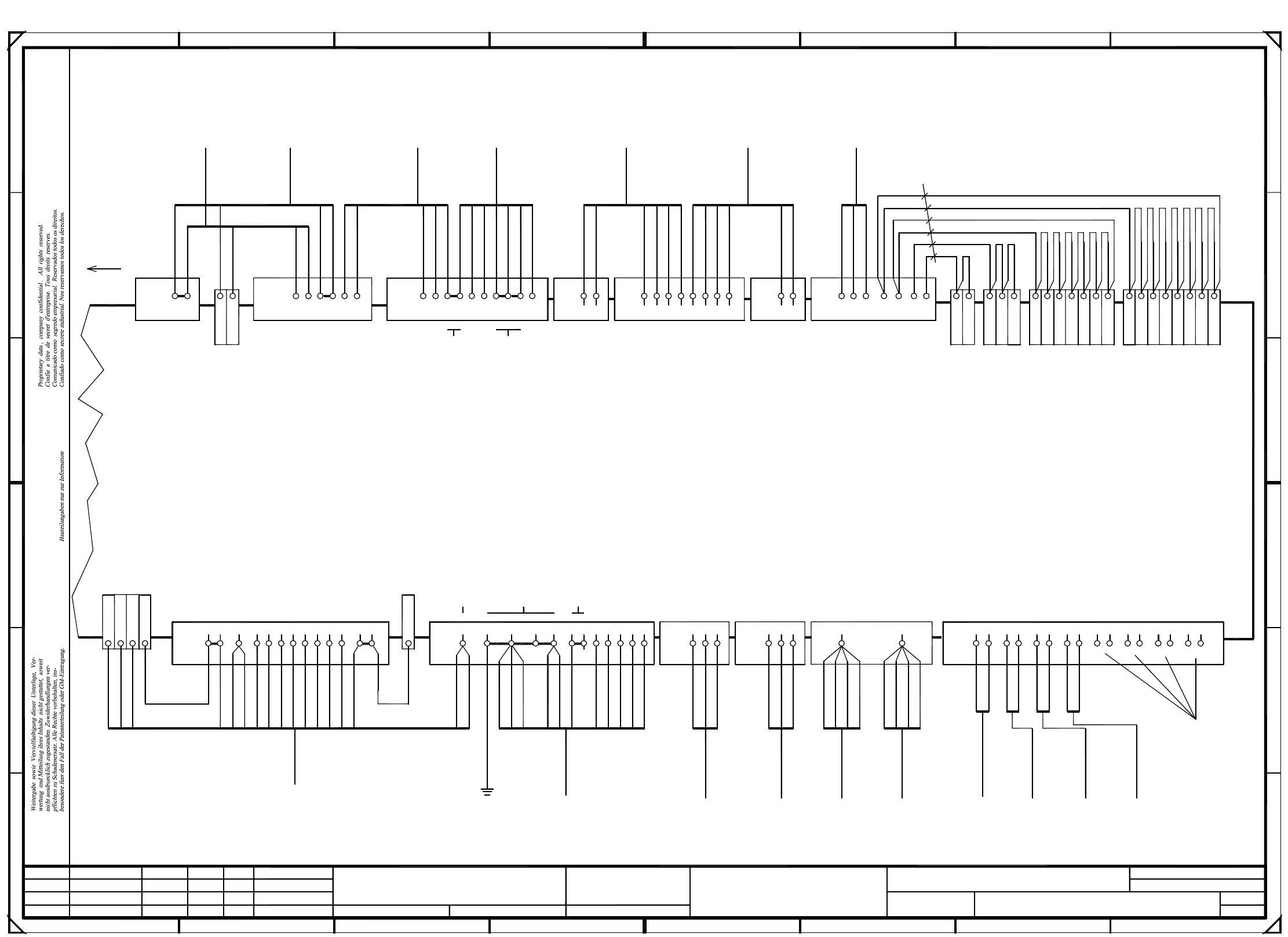
3 SIPLACE 80S-20 Circuit Diagrams 84
00344265-020101LD3 Terminal panel (left-hand side) (Sh. 2 of 2)
wh&br
gn&ye
bn
pk
gy
ye
gn
wh
gn
ye
bn
wh
pk
gy
GND bus bar
ye
bl&rd
bk
pk
gy&pk
rd&bl
bn
wh
vio
gy
gn
bk
wh/gn/gy/bl
wh/gn/gy/bl
ye/pk/rd
bn
ye/pk/rd
bn
bn
bn
wh
bn
bn
wh
wh
wh
gy
gn
ye
pk
gn
pk
gy
ye
From feeder crash sensor, right CO-table, S4
To feeder crash sensor, right CO-table, S4
From feeder crash sensor, right CO-table, S3
To feeder crash sensor, right CO-table, S3
From feeder crash sensor, left CO-table, S2
To feeder crash sensor, left CO-table, S2
From feeder crash sensor, left CO-table, S1
To feeder crash sensor, left CO-table, S1
To feeder crash sensor, Spare 4
From feeder crash sensor, Spare 3
To feeder crash sensor, Spare 3
From feeder crash sensor, Spare 2
To feeder crash sensor, Spare 2
From feeder crash sensor, Spare 1
To feeder crash sensor, Spare 1
From CO-table (E-S-L)
+30V unswitched
+30V switched
+30V switched
+30V switched
+30V unswitched
+30V unswitched
+30V switched
wh
gn
bn
wh&gr
gy&br
pk&bn
bl/bk
+30V switched
=
SIEMENS AG
+
F
E
454
5ki P
+12V
X
8X
D
+24V
P
2
2kf
2ke
5
U
+24V
2011
+24V
+24V
+24V
+24V
+24V
X
76
2kd
8
1
X212
00322111-xx
X211
7
*(00344213-xx)
*(00344261-xx)
*(00344260-xx)
*(00344277-xx)
*(00344276-xx)
4208 5
2kc
X210
21
00xxxxxx-xx
6
+
X210
2
32 8
00xxxxxx-xx
00xxxxxx-xx
00xxxxxx-xx
25
X212
26 26
20 6
27 27 28 28 29 29 30 30 31 31 32
Ha
Leh
02
01
02.09.99
02.10.98
02.09.99
Haas
#
00344265-020101LD3
01 02.09.99
PL EA1 E
Ha
Date
Check.
Author
Creat. byCreat. f.Orig.NameModified DateStatus Stand.
Sh.
Sheet
SMD Placement System SIPLACE 80S20/S23
Document status
Product status
Function status
Circuit diagram, terminal panel
lefthand side
00322104-xx
00303617-xx
(00321421-xx)
Continued on
sheet 1
Hood switch
Option
succeeding
machine
Output conveyor
Hood switch
the jumper
Warning!
(connection rail)
If a hood switch
is connected
has to be removed.
To terminal panel
righthand side
To
Servo unit
***
***
00322105-xx
00322333-xx
0.5mm²
wh
wh
bl/bk
bl/bk
gy
bn&bk
multiplexer
To video
righthand side
WPC interface
To
lefthand side
To
WPC interface
when wiring the module.
In SIPLACE 80S23 machines
both WPW interfaces ***
In SIPLACE 80S20 machines
Jumpers X211 4-5 and
X211 6-7 have to be inserted
these cables are not available.
are available.
Please note:
0.5mm² 0.5mm²
6.0mm²
Ground
(Frame)
Power supply, switched
To
apply to the F5-HM machine.
in brackets
The numbers
* Please note:
Conversion board
Gantry 1
Conv. board
Gantry 2
Conv. board
To
Gantry 1
To
Gantry 2
Conv. board
To To
Control unit
To
S1 switch
Feeder
Crash
CO-table, le
Sensor
Option:
Crash
S2 switch
CO-table, le
Sensor
Feeder
Option:
Crash
S3 switch
CO-table, ri
Sensor
Feeder
Option:
Crash
S4 switch
CO-table, ri
Sensor
Feeder
Option:
Terminals X212/25
to X212/32 are jumpered
(factory setting).
can be connected.
crash sensors
4 more feeder
Please note:
From signaling circuit, protective switch 6
From signaling circuit, protective switch 5
From control circuit, prot. switch 6
To control circuit, prot. switch 6
To control circuit, prot. switch 5
From control circuit, prot. switch 5
K1 signaling circuit
K2 signaling circuit
+30V unswitched
wh
wh
bn
bn
gn
gy
ye
ye
gn
ye
rd
bk
bn
pk
gn
bl
Software release signaling circuit (K3 monitoring)
Control ON, K2 signaling circuit
K3 safety contactor, GND
K3 software release
From Start button to K1
External emerg.-stop circuit (WPC)
Control On, K1 signaling circuit
To Start button from K2
From emerg.-stop circuit to K2
To Start button from K1
From software relay K3
From Start button to K2
Control On, K1 signaling circuit
To software relay K3
Control ON, K2 signaling circuit
Control ON, K2 signaling circuit
Control On, K1
wh&ye
wh&gn
bl&bk
bl&bk
vio
gn
ye
gy&pk
gy
bn&gn
rd&bl
bn
ye&br
bl&bk
bl
bk
wh
From signaling circuit, Emerg.-stop button
To signaling circuit, Emerg.-stop button
From signaling circuit, Emerg.-stop button
To signaling circuit, Emerg.-stop button
To WP changer (E-S-L)
From WP changer (E-S-L)
From WP changer (E-S-L)
To WP changer (E-S-L)
External emerg-stop GND
External emerg-stop GND
External emerg.-stop
External emerg.-stop
gn&ye
gy&pk
X
00321790-xx
-15V
+5V
X5kg
+12V
2ke
12
X210
3
3
+24V
4
P
4
00321426-xx
4
X
GND
43
GND
GND
00305818-xx
GND
+24V
X
3
+24V
M
GND
X
GND
F
E
13
X212
M
10
00321789-xx
P5kg
M
00321787-xx
+24V
X
00321788-xx
+24V
P
G
1
2kb
2ka
2kf
10 3
+24V
+5V
+24V
00321086-xx
22
P
C
B
2kd
2kc
+24V
XM
22
2
-15V
21 21
2kb
2
X211
33
318
M
3
5kg
GND
+5V
6333
X
X
X212
-12V
7
7
2kd
15
00321113-xx
14 21
1
GND
+5V
3
1
X
+
2ka
2kc
2kc
XP
X
16
X
GND
GND
19
2kd
14
GND
+24V
7
X
X
8
10
13-14 X211
X212
4
13
X
00305817-xx
810
00300182-xx
C
B
A
2
5
X
1234
X
974
17
GND
P
+15V
8
X212
10
M5ki
D
X
MX
34
X
M
+24V
5kiX
5kg
-X
2kd
00301485-xx
4
4
2kd
+8V
22 2
+5V
A
+24V
X211
21
X
00306880-xx
U
6
GND
2kb
G5ki
00322112-xx
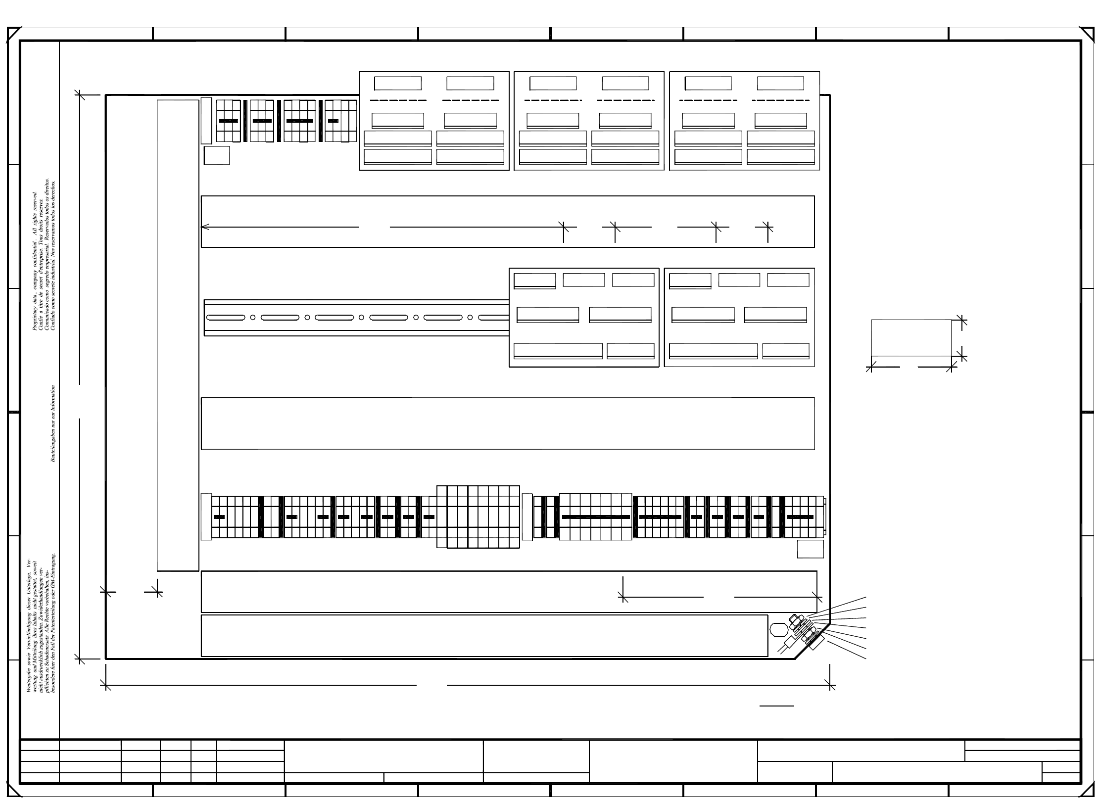
3 SIPLACE 80S-20 Circuit Diagrams 85
00344265-020101TD3 Terminal panel (left-hand side)
PL EA1 E5
02.09.99
02.09.99
00344265-020101TD3#
Haas
02.09.99
02.10.98
22 22
23 24
25
1
0V
0V
X1kd
5
EA
8
X1ki
XX
A4
240mm
1
1
2
X
X2kdA
2
XX
80mm
A3
2
2
6
30mm
X
XX
20 20
X2kd
X
3
X2ke
6
16
18
18
17
6
7
X2kd
7
21 21
A
X1kf X1ke
X2kf
4
00344265-02
Siemens PLEA
A
19
X1ka
X2kb X2ka
10
END
X1kb
19
1
X212
15
A
26
27 28
29 30
31 32
X7kg
XX
8
20
40
AA-BBBB-CCCC
X2kf
X2kc
6
X
1
3
3
3
3
3
8
1
30mm
45
5
4
10
130mm
500mm
2
1
E
3
4
X
X2kg
E
D
C
B
3
35mm
8
9
5
X2kcX2ke
X2kf X2ka
X2ke
3
3
4
13
14
16
6
X211
1
7
8
X
F
B
12
4
X
X4ki
X
A
3
3
3
4
4
10
10
7
X2kb
5
X2kc
1
XX
X210
F
E
X1kc
X7ki
17
X4kg
X
X5kg X6kg
X1kg
X
8
9
10
E
12
B
C
D
11
X2kaX2kb
X
X3kg
0V
0V
0V
0V
0V
4
A2 A1
A6
4
X2ki
420mm
X3ki
2345
01
01
02
Leh
Ha
Ha
X5ki X6ki
C
67
Date
Check.
Author
Creat. byCreat. f.Orig.NameModified DateStatus Stand.
Sh.
Sheet
SMD Placement System SIPLACE 80S20/S23
Document status
Product status
Function status
Terminal panel, lefthand side
Note 3:
Length for cable ducts +/- 5mm !
CCCC = series number
BBBB = date (year/month/day)
AA = manufacturer/location
VA-F-510-001 guideline
Font size: 2.5mm, material
Assembly inscription acc. to
Scotchcal 3698-E
(Color A1 RAL 9006)
acc. to SN 37040
=
SIEMENS AG
+
acc. to SN 01007
acc. to construction specs 00343603, sh. 2
DIN 125 washer
Screw
SN 70093 contact washer
DIN 439 nut
Annular cable lug
Ground connection
DIN 7980 split washer
DIN 439 nut
C: ground label
(ye&gn)
B: inspection label
Note 1:
to be fitted:
A: identification label
The following labels have
(Please note: X means to break off one rib from the cable duct)
Cable duct: 65x30 l=425mm
Cable duct: 65x46 l=425mm
Cable duct: 65x30 l=400mm
(Please note: XXX means to break off three ribs from the cable duct)Cable duct: 65x30 l=325mm
(Please note: X means to break off one rib from the cable duct)
Cable duct: 65x46 l=425mm