cp45头部故障判断.pdf - 第11页
1. Head Module Ver. Date CP45 CP45NEO 00 2004/11 O O 1-1 1-4.Mirror Setting Procedure *T o o l s a) Calibration Tool ( in ANC 1st p ocket ) 2EA b) Hex Wrench (2.5mm) *P a r t s 1) Simple Procedure (1) With Mirror Support…
1. Head Module
Ver. Date CP45
CP45NEO
00 2004/11 O O
1-1
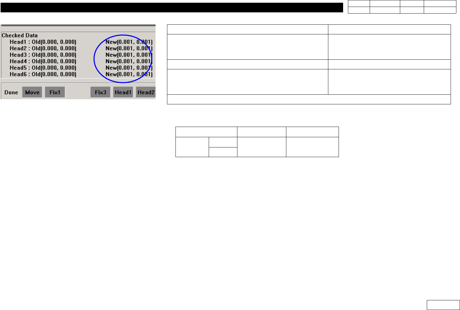
5) Check Calibration Result(Ref. Fig. 1-3-4 New Checked Data) Compared to the Standard below.
6) Click 'Update' Calibration to Apply New Offset Data if the Result is within the Standard,
and otherwise Check the Assembled Condition of Mirror to Re-assemble Mirror and Proceed
Calibration if Necessary.
Message
Process
'Next remove the calibration tool from head 1
Click[Next] for moving down head.
After moving, remove the tool manually
Click Next
=> Head1 Goes Down (Remove Tool)
Z-axis moving down Please wait for a moment
Stand by Until Next Message
'Next remove the calibration tool to head 2
Click[Next] for moving down head.
After moving, remove the tool manually
Click Next
=> Insert Calibration Tool in Head2
Proceed Calibration to Head6 in the Same Way
Item FOV 25mm FOV 15mm
Tolerance
X
+ - 0.75mm + - 0.45mm
Y
Fig.1-3-4 Head-Fly Camera Offset calibration
result (Checked data : New)
1. Head Module
Ver. Date CP45
CP45NEO
00 2004/11 O O
1-1
1-4.Mirror Setting Procedure
*Tools
a) Calibration Tool ( in ANC 1st pocket ) 2EA
b) Hex Wrench (2.5mm)
*Parts
1) Simple Procedure
(1) With Mirror Support and Mirror arm(left,right) Assembled, Re-assemble w/o Height Diff.
(Ref. Fig.1-4-1)
(2) Re-calibrate Head-Fly Offset
2) Precise Procedure
(1) Insert Calibration Tool in Head1 and Head6
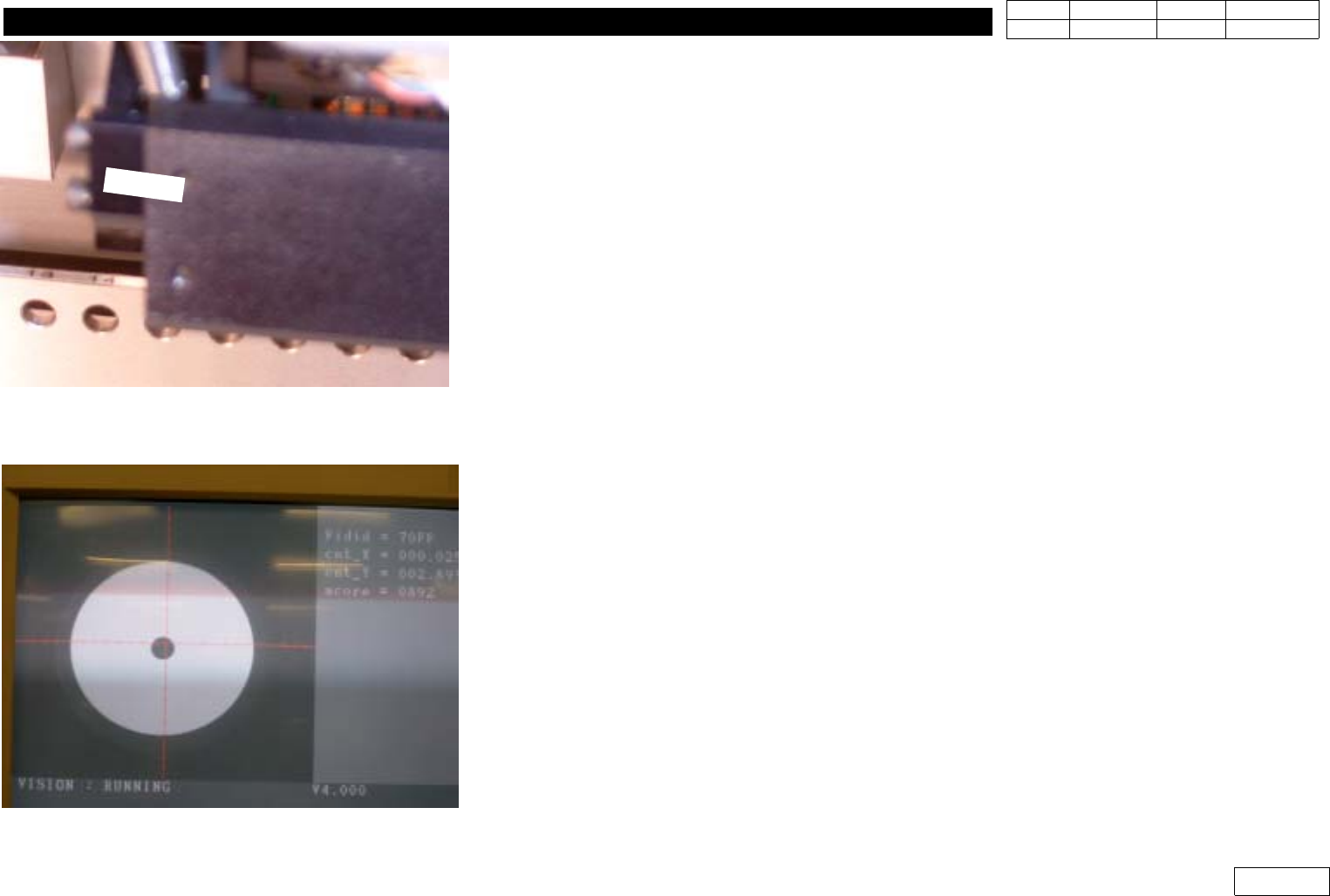
(2) Move Tool to Align Height :
- Select Arbitrary Part(1005) and Part Data Edit Screen(Align Data Screen)
- Select 'Move', 'Prepare Aligne Test'
- Click Yes after 'Z and Mirror axis will move or Head Block will move to the Fix Camera
Position' Message
- Z-axis and Mirror Move to Sensing Position
- Adjust Mirror Support to Make the Monitor Cross Line and the Center of Calibration Tool
Coincide Each Other as Watching FV#1 and FV#6d Alternately in Vision Monitor, and
Fasten Bolt
* Adjustments after this work
- Head-Fly offset Calibration.(Ref. 1-3)
- Check Swing Mirror Motor Home Offset(Ref. 1-19).
- Proceed Vision Nozzle Check.(Ref. 1-12)
Fig.1-4-1 Ckeck the assmbled status
between support and arms
Fig.1-4-2 Check the deviation of tool center
1. Head Module
Ver. Date CP45
CP45NEO
00 2004/11 O O
1-1
1-5.Can Head Board Ass'y Replacement Procedure
*Tools
a) +Screwdriver
b) Spanner (* mm) 2EA
*Parts
a) CAN HEAD BOARD Ass'y (J9060062B)
1] Separate Board plate(J7154110B)
2) Remove Various Connectors at Board
3) Remove Hex Support
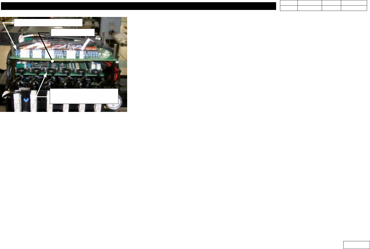
4) Replace Head Illumination Control Board(=Can Head Board Ass'y)
Be Careful Not to Leave Out Isolation Sheet (Ref. Fig. 1-5-1)
5) Fasten Board Using Hex Support
6) Check PCB Layout in Fig. 1-5-2 and the Lable of Cable to Connect Connector to Original
Location
7) Assemble Board Plate to Complete Replacement
* Adjustments after this work
-None
.
Fig.1-5-1 Can head board ass'y
CAN HEAD Board Ass'y
HEAD ILLUMINATION
CONTROL BOARD Ass'y
Isolation Sheet