cp45头部故障判断.pdf - 第16页
1. Head Module Ver. Date CP45 CP45NEO 00 2004/11 O O 1-1 1-7.Swing M otor /Swing Timing belt Replacement, Check *T o o l s a) Wrench(4mm, 3mm,2.5mm) , Z-Phase dete cting Tool *P a r t a) TIMI NG BELT [300-3 GT-6] (J 6602…
1. Head Module
Ver. Date CP45
CP45NEO
00 2004/11 O O
1-1
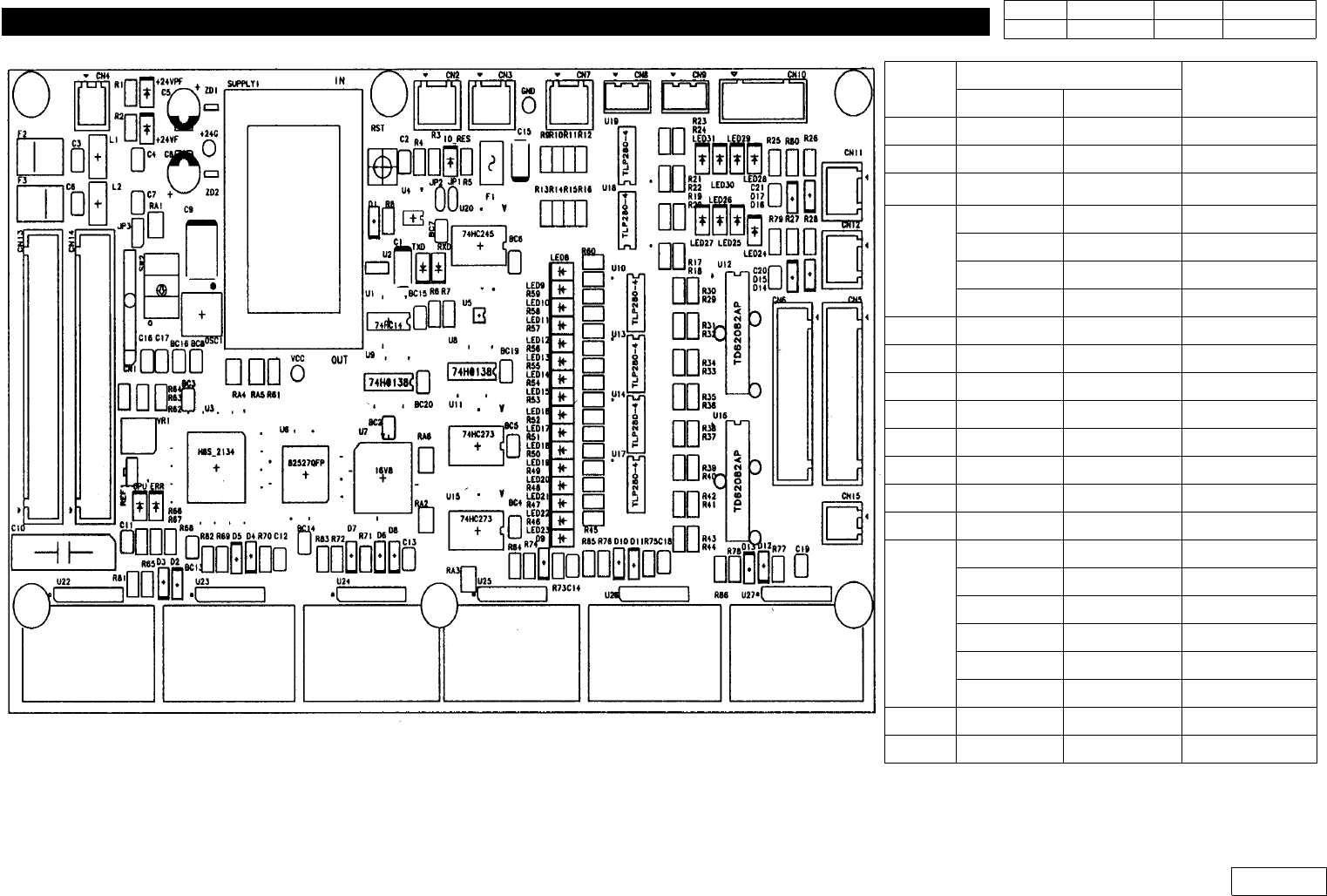
Fig.1-6-2 PCB layout (Head Illumination Control Board)
Cable
Remark
Code Type
CN1
CN2
CN3 J9061329B MK-CA07
CN4
J9061221B MK-HI01
J9061757A MK-HI01CE CE OPTION
J9061207B MK-HD01
J9061758A MK-HD01CE CE OPTION
CN5 J9061208B MK-HD02
CN6 J9061209B MK-HD03
CN7 J9061210B MK-HD04
CN8
CN9
CN10 J9061212B MK-HD06
CN11
CN12
CN13
J9061213B MK-HD07
J9061215B MK-HD08
J9061216B MK-HD09
J9061217B MK-HD11
J9061218B MK-HD12
J9061217B MK-HD11
CN14 J9061219B MK-HD13
CN15 J9061220B MK-HD14
1. Head Module
Ver. Date CP45
CP45NEO
00 2004/11 O O
1-1
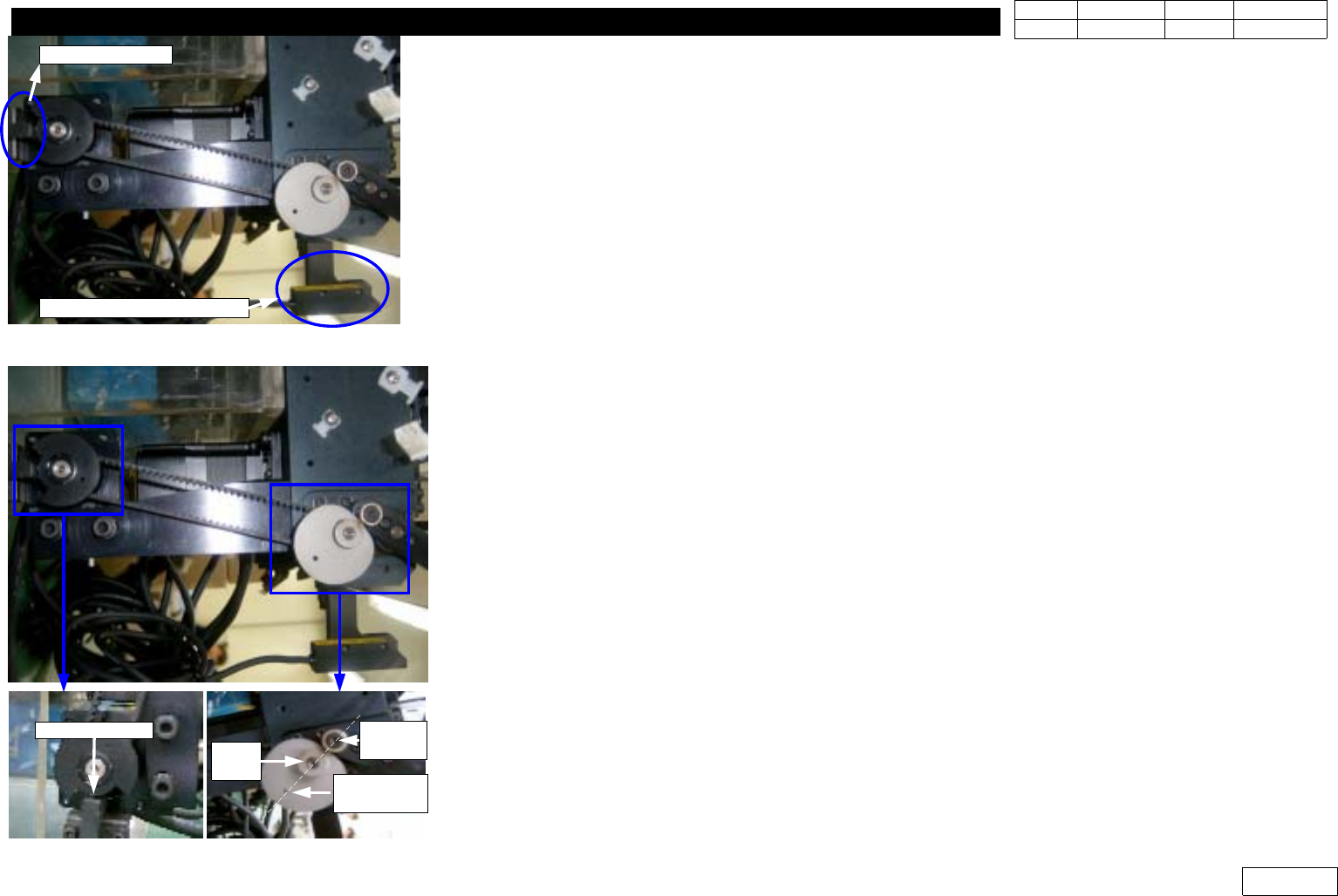
1-7.Swing Motor /Swing Timing belt Replacement, Check
*Tools
a) Wrench(4mm,3mm,2.5mm), Z-Phase detecting Tool
*Part
a) TIMING BELT [300-3GT-6] (J6602034A)
b) CP45NEO : S Motor Cable Ass'y (J9080120B)
CP45FV : Q-Swing Motor Cable Ass'y (J9075961B)
1) Separate Teaching Beam Sensor and Swing Home Sensor for Replacement
(Ref. Fig. 1-7-1)
2) Separate Swing Motor Fastened with Camera Bracket
3) Separate Pulley and Sensor Dog from Motor
4) Separate Bracket and Isolator from Motor
5) Assemble Bracket and Isolator to New Motor, and Assemble Pulley and Sensor Dog
6) Assemble This to Camera BracketandFitinBelt
7) Assemble Separated Teaching Beam Sensor and Swing Home Sensor to Original Position
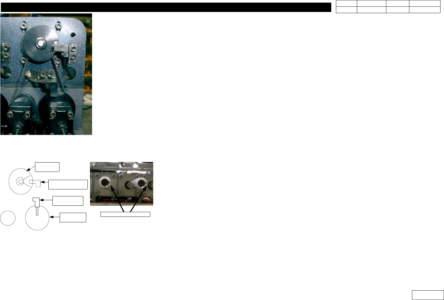
8)AlignHome(Ref.Fig1-7-2)
Detect Motor Z When Aligning Hole Center of CAM, Center of CAM Shaft, Center of CAM Follow
are on a Straight Line, and Adjust Position to Set Dog of Home Sensor to Center
9) Adjust Belt Tension
* Adjustments after this work
-
Head-Fly Offset
- Swing Mirror Motor Home offset(1-19).
Fig.1-7-1Swing Timing Belt
Teaching Beam Sensor
Home Sensor
Fig.1-7-2 Aligning Method
Center of Dog
CAM Aligning
Hole
CAM
Shaft
CAM
Follower
1. Head Module
Ver. Date CP45
CP45NEO
00 2004/11 O O
1-1
1-8.Theta-axis Motor/Timing Belt Replacement, Check
*Tools
a) Wrench, Nozzle Holder Setting Jig
*Part
a) TIMING BELT [308-2GT-4] (J6602024A)
b) Theta Motor Ass'y + Thata Motor Driver
1) Loosen the Fastened Bolt 4EA to Separate Motor
2) Separate Pulley and Sensor Dog
3) Replace with Mew Motor to Assemble Pulley and Sensor Dog
4) Assemble Thata-axis Belt to Pulley and Motor to Bracket
5) Set the Position of Sensor Dog(Home Sensor,Origin Sensor),
and at the Same Time Set the Position of Nozzle Holder Groove the Same Way (Ref. Fig 1-8-2)
=> Generally the Groove of Nozzle Holder is Arranged with Naked Eyes, but Nozzle Holder Setting
JigisUsedforSquareNozzletoEasetheWork.
6) Adjust Tension (Refer the Tension of Other Spindle)
7) If the Replacement of Belt is Necessary, Separate Slide Arm and Joint from Spindle to Replace
Belt Through the Gap.
* Adjustments after this work
- Offset-R Check and Input(Ref. 1-11)
Fig.1-8-1 Thata axis Timing Belt
Motor
Pulley
Thata Origin
Sensor(TH1-OGR)
Pulley-
Thata 2
Home Sensor
(TH1-H)
Fig.1-8-2 Thata Axis sensor and nozzle
holder groove position
Align the Groove