cp45头部故障判断.pdf - 第18页
1. Head Module Ver. Date CP45 CP45NEO 00 2004/11 O O 1-1 1-9. Z-axis Motor/Timing Belt Replacement, Check *T o o l s a) Wrench *P a r t a) TIMING BELT [340-2 GT-12] (J6 602023A) b) Z-axis Motor 1) In Case the Fixture to …
1. Head Module
Ver. Date CP45
CP45NEO
00 2004/11 O O
1-1
1-8.Theta-axis Motor/Timing Belt Replacement, Check
*Tools
a) Wrench, Nozzle Holder Setting Jig
*Part
a) TIMING BELT [308-2GT-4] (J6602024A)
b) Theta Motor Ass'y + Thata Motor Driver
1) Loosen the Fastened Bolt 4EA to Separate Motor
2) Separate Pulley and Sensor Dog
3) Replace with Mew Motor to Assemble Pulley and Sensor Dog
4) Assemble Thata-axis Belt to Pulley and Motor to Bracket
5) Set the Position of Sensor Dog(Home Sensor,Origin Sensor),
and at the Same Time Set the Position of Nozzle Holder Groove the Same Way (Ref. Fig 1-8-2)
=> Generally the Groove of Nozzle Holder is Arranged with Naked Eyes, but Nozzle Holder Setting
JigisUsedforSquareNozzletoEasetheWork.
6) Adjust Tension (Refer the Tension of Other Spindle)
7) If the Replacement of Belt is Necessary, Separate Slide Arm and Joint from Spindle to Replace
Belt Through the Gap.
* Adjustments after this work
- Offset-R Check and Input(Ref. 1-11)
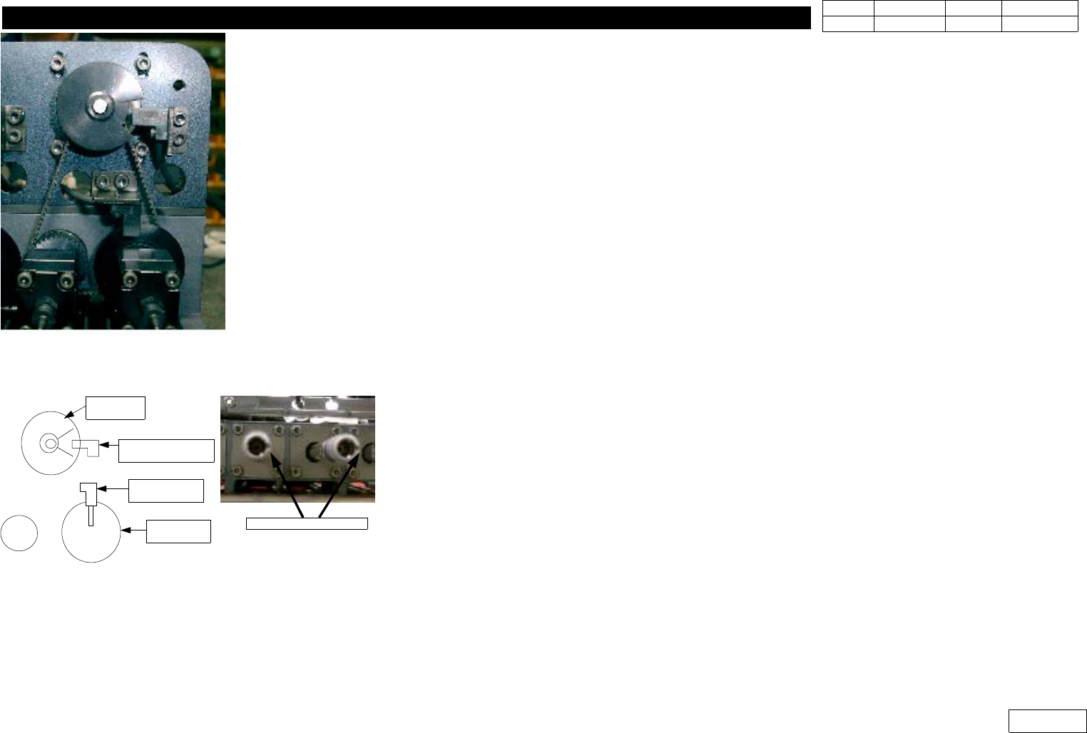
Fig.1-8-1 Thata axis Timing Belt
Motor
Pulley
Thata Origin
Sensor(TH1-OGR)
Pulley-
Thata 2
Home Sensor
(TH1-H)
Fig.1-8-2 Thata Axis sensor and nozzle
holder groove position
Align the Groove
1. Head Module
Ver. Date CP45
CP45NEO
00 2004/11 O O
1-1
1-9. Z-axis Motor/Timing Belt Replacement, Check
*Tools
a) Wrench
*Part
a) TIMING BELT [340-2GT-12] (J6602023A)
b) Z-axis Motor
1) In Case the Fixture to Find Servo Motor Z-Phase is Not Available, Indicate the Position of Motor
Z-PhaseatHeadFrameBeforeSeparatingMotortobeReplaced(Ref.Fig1-9-1-1)
- Lift the Z-axis to the Position Z-Home Sensor Senses (Ref. (1))
- Check the Z-Phase Mark of Z-Motor to be Replaced (Ref. (2))
-MarkatHeadBodyintheSameDirection(Ref.(3))
- Assembly of Z-Phase of New Z-Motor to the Same Position This Way Enables the Replacement
w/o Checking Z-Phase Additionally
2) Loosen the Bolt Fastened at Upper Head#1,3,5 Motor(Check Bolt Specification), and Separate Motor
3) Assemble New Motor(Ref. Fig 1-9-3), and Fix Belt at Pulley at This Time
(Check the Position of Z-Phase to Assemble in the Opposite Direction of 'Procedure 1)')
4) (In Case Z-Phase Detecting Fixture is Available)Use Detecting Fixture to Assemble Motor Z-Phase
so that Z-axis Home Sensor can be On Right After the Detection of Motor Z-Phase
(Ref. Fig 1-9-1)
=> After the Encoder Cable of Motor is Connected, Z-Phase is Detected When the Lamp of Fixture
is On as Running Motor
5) For Lower Head#2,#4,#6, FV and Swing Motor and Adjacent Pulley Should be Separated First to
Separate Motor
6) After This, Replacement Procedure is Same(Ref. Fig 1-9-2 for Sub Assembly of Motor)
7) Refer Adjacent Z-axis Belt of Head to Adjust the Tension of Z-axis Belt
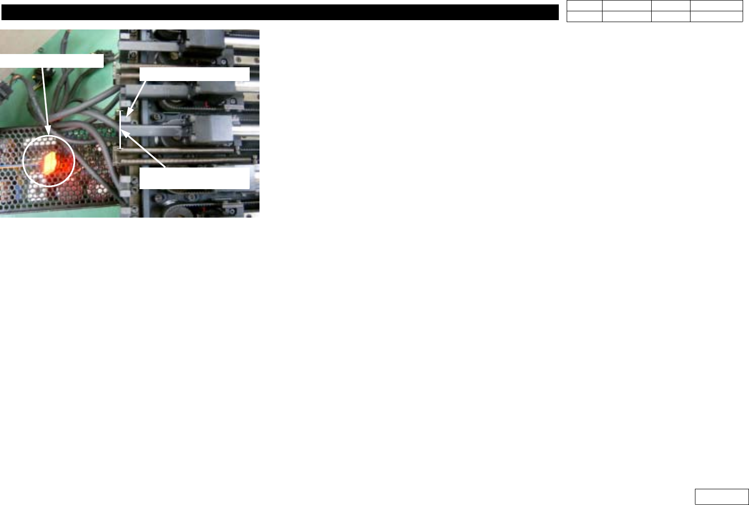
Fig.1-9-1 Detacting Z-Phase and
the position of Z-Home dog
Z Axis Home Sensor
When detect Z-Phase,
that time the position
of Z- home Dog
1. Head Module
Ver. Date CP45
CP45NEO
00 2004/11 O O
1-1
Refer Fig 1-9-4 for the Position to Measure Belt Tension
* Adjustments after this work
- Head(Fly) Camera Calibration.(Ref. 2-3)
- Head offset Setting.(Ref. 2-16)
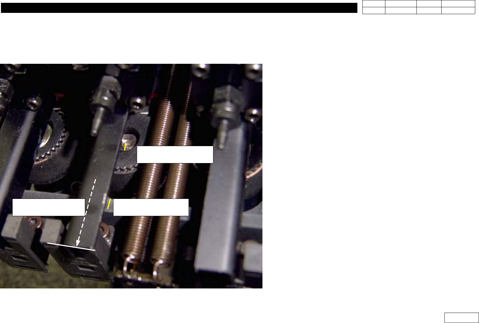
(1) Push the Z-axis upper
position to detect the sensor
(2) Check the Z-Phase mark
on the motor shaft.
(3) Mark the Z-Phase on the
Head body
Fig.1-9-1-1 Z-phase mark procedure for the Z-Motor.